8 Motor control
This chapter contains all funcons and sengs relevant for the motor control.
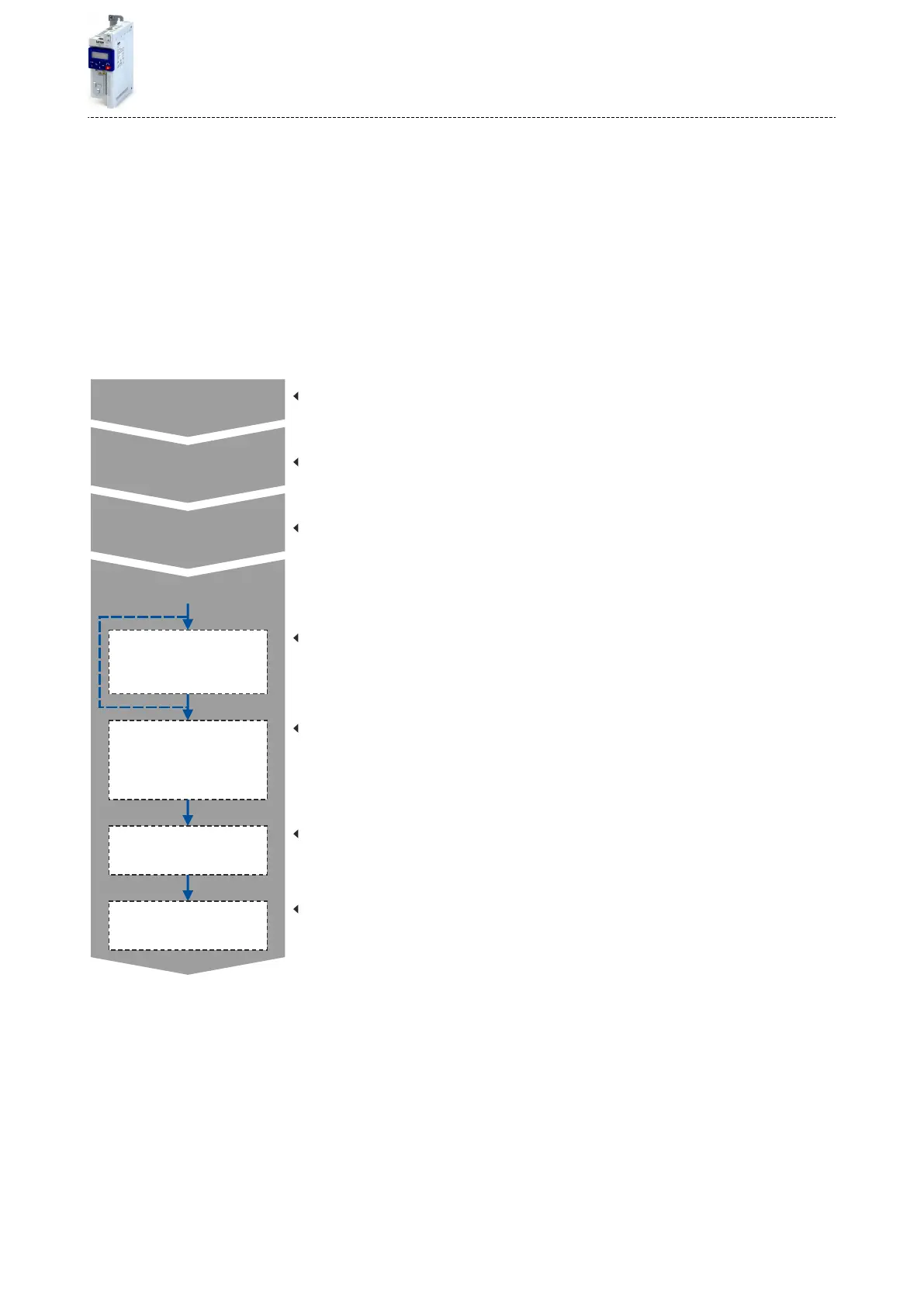
Basic procedure of commissioning the motor control
In the rst step, the rated data of the motor must be set. The other steps depend on the
respecve applicaon case.
There are several opons for seng the motor data and opmising the control loops. Basi-
cally, you can select between a manual and an automac process. Whether a seng can be
applied or not depends on the motor (Lenze motor yes/no) and the applicaon. If possible,
always use the possible seng listed rst in the following diagram since this one leads to the
most accurate results.
Parameterisable functions:
V/f voltage boost, skip frequencies, optimisation of the stalling behaviour,
slip compensation, oscillation damping
Options:
V/f characteristic control (open-loop) (default setting), V/f characteristic control (closed-loop),
servo control, sensorless control, sensorless vector control
Possible settings:
a) Identifying data automatically (by inverter)
b) Calibrating data automatically (by inverter or engineering tool)
c) Loading preset inverter characteristics
Possible settings:
a) Identifying data automatically (by inverter)
b) Entering data manually
Possible settings:
a) Identifying data automatically (by inverter)
b) Entering data manually
Possible settings:
a) Identifying data automatically (by inverter)
b) Using data from the motor catalogue
c) Calibrating data automatically (by inverter or engineering tool)
d) Entering data manually
Possible settings:
a) Using data from motor catalogue
b) Entering data manually (e.g. from the nameplate)
Optimisation of the control loops
Optimisation of motor control
Motor control selection
Setting of motor data
Speed controller
Motor controller
settings
Motor
equivalent circuit data
Inverter characteristic
•
Motor data ^ 114
•
Motor control selecon ^ 115
•
Opmisaon of motor control ^ 129
•
Opmisaon of the control loops ^ 140
•
Motor rotang direcon ^ 159
•
Switching frequency changeover ^ 160
•
Motor protecon ^ 161
Motor control
113

 Loading...


