Parameter Name / value range / [default seng] Info
0x400C:001
(P593.01)
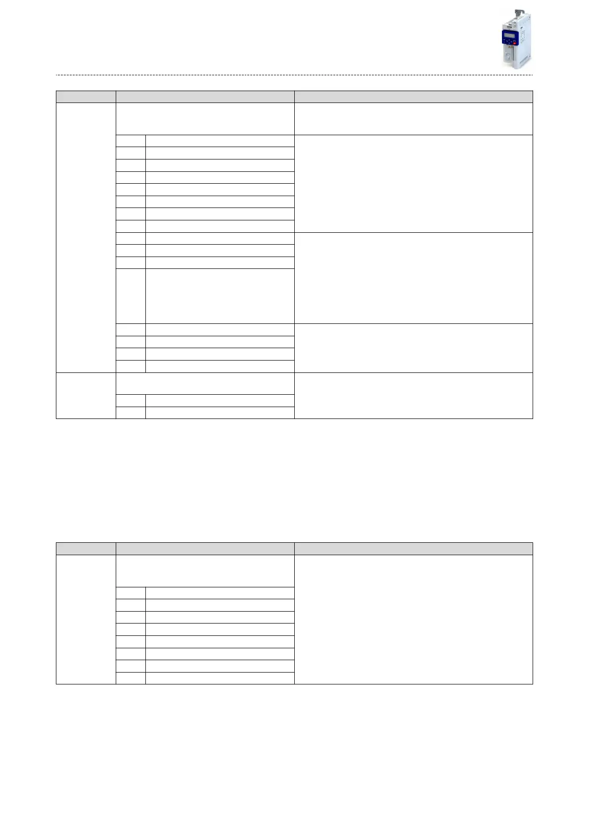
Process output data: AC Drive status word
(Process data OUT: AC status word)
•
Read only
Mappable status word with bit assignment in compliance with
EtherNet/IP™ AC drive prole.
Bit 0 Fault/Trip acve
Bit 1 Warning acve
Bit 2 Running forward
Bit 3 Running reverse
Bit 4 Ready
Bit 5 Network control acve
Bit 6 Network setpoint acve
Bit 7 At Reference
Bit 8 Prole-State bit 0 The drive status is coded as follows:
0: Manufacturer-specic (reserved)
1: Startup (Drive inialisaon)
2: Not_Ready (Mains voltage switched o)
3: Ready (Mains voltage switched on)
4: Enabled (Drive has received run command)
5: Stopping (Drive has received stop command and is stopped)
6: Fault_Stop (Drive is stopped due to a fault)
7: Faulted (Faults have occurred)
Bit 9 Prole-State bit 1
Bit 10 Prole-State bit 2
Bit 11 Prole-State bit 3
Bit 12 Process controller acve
Bit 13 Torque mode acve
Bit 14 Current limit reached
Bit 15 DC braking acve
0x6402 Motor type
•
From version 02.00
AC motor type
•
Motor Data Object (0x28) - instance aribute 3
3 PM synchronous
7 Squirrel cage inducon
9.2.3 Lenze LECOM prole
For connecon to Lenze inverters with a LECOM control word (C135) and LECOM status word
(C150), the parameters listed in the following can be mapped to network registers.
Details
•
The mapping entry for the LECOM control word is 0x400B0210.
•
The mapping entry for the LECOM status word is 0x400C0210.
•
General informaon about the process of data mapping can be found in the chapter of the
same name for the corresponding network.
Parameter Name / value range / [default seng] Info
0x400B:002
(P592.02)
Process input data: LECOM control word
(Process data IN: LECOM ctrl word)
0x0000 ... [0x0000] ... 0xFFFF
Mappable control word with bit assignment in compliance with code
C135 of the 8200 Lenze inverter.
Bit 0 Acvate preset (bit 0)
Bit 1 Acvate preset (bit 1)
Bit 2 Reverse rotaonal direcon
Bit 3 Acvate quick stop
Bit 9 Disable inverter
Bit 10 Acvate user fault
Bit 11 Reset error (0-1 edge)
Bit 14 Acvate DC braking
Conguring the network
Predened process data words
AC Drive Prole
194

 Loading...


