13.8 Triggering a user-dened fault
The "Acvate fault 1" and "Acvate fault 2" funcons serve to set the inverter from the proc-
ess to the error status.
Details
If, for instance, sensors or switches are provided for process monitoring, which are designed
to stop the process (and thus the drive) under certain condions, these sensors/switches can
be connected to free digital inputs of the inverter. The digital inputs used for the sensors/
switches then have to be assigned to the funcons "Acvate fault 1" and "Acvate fault 2" as
triggers.
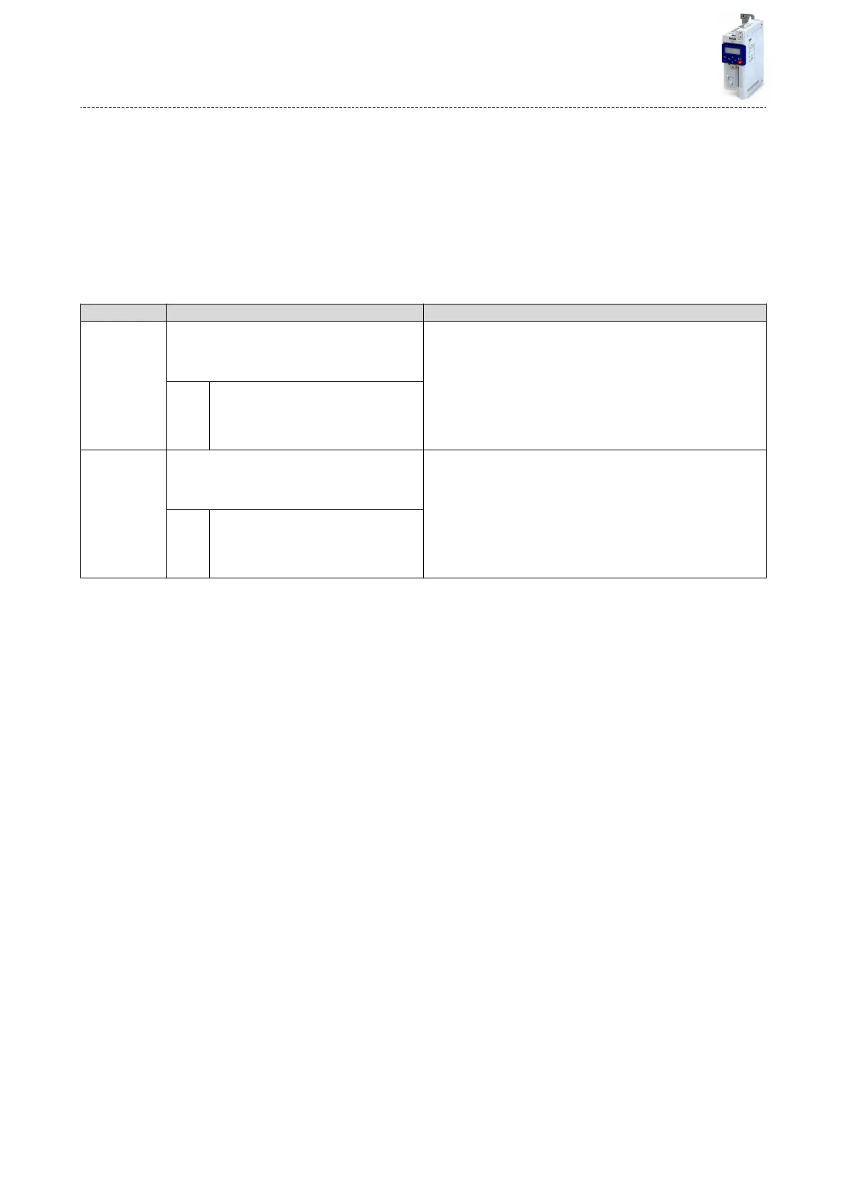
Parameter Name / value range / [default seng] Info
0x2631:043
(P400.43)
Funcon list: Acvate fault 1
(Funcon list: Fault 1)
•
For further possible sengs, see parameter
0x2631:001 (P400.01). ^ 351
Assignment of a trigger for the "Acvate fault 1" funcon.
Trigger = TRUE: Trigger user-dened error 1.
Trigger = FALSE: no acon.
Notes:
•
Aer the error is triggered, the motor is brought to a standsll with
the quick stop ramp. The inverter is then disabled.
Associated error code:
•
25217 | 0x6281 - User-dened fault 1
0 Not connected
0x2631:044
(P400.44)
Funcon list: Acvate fault 2
(Funcon list: Fault 2)
•
For further possible sengs, see parameter
0x2631:001 (P400.01). ^ 351
Assignment of a trigger for the "Acvate fault 2" funcon.
Trigger = TRUE: Trigger user-dened error 2.
Trigger = FALSE: no acon.
Notes:
•
Aer the error is triggered, the motor is brought to a standsll with
the quick stop ramp. The inverter is then disabled.
Associated error code:
•
25218 | 0x6282 - User-dened fault 2
0 Not connected
Example
An example of the operang mode can be found in the chapter "Reset error". ^ 384
Related topics
4Error handling ^ 90
Flexible I/O conguraon
Triggering a user-dened fault
392

 Loading...


