11.4.2 Example 2: Automac DC braking when the motor is stopped
In order that the DC braking is automacally acve when the motor is stopped, the corre-
sponding operang threshold must be set in 0x2B84:003 (P704.03).
•
Aer a stop command, the motor is rst decelerated as set. Only if the output frequency
falls below the set operang threshold, the inverter stops the deceleraon and acvates
DC braking.
•
DC braking is carried out with the braking current set in 0x2B84:001 (P704.01) for the hold
me set in 0x2B84:002 (P704.02).
•
The exact behaviour depends on the stop method set in 0x2838:003 (P203.03).
Stop method = "Standard ramp [1]"
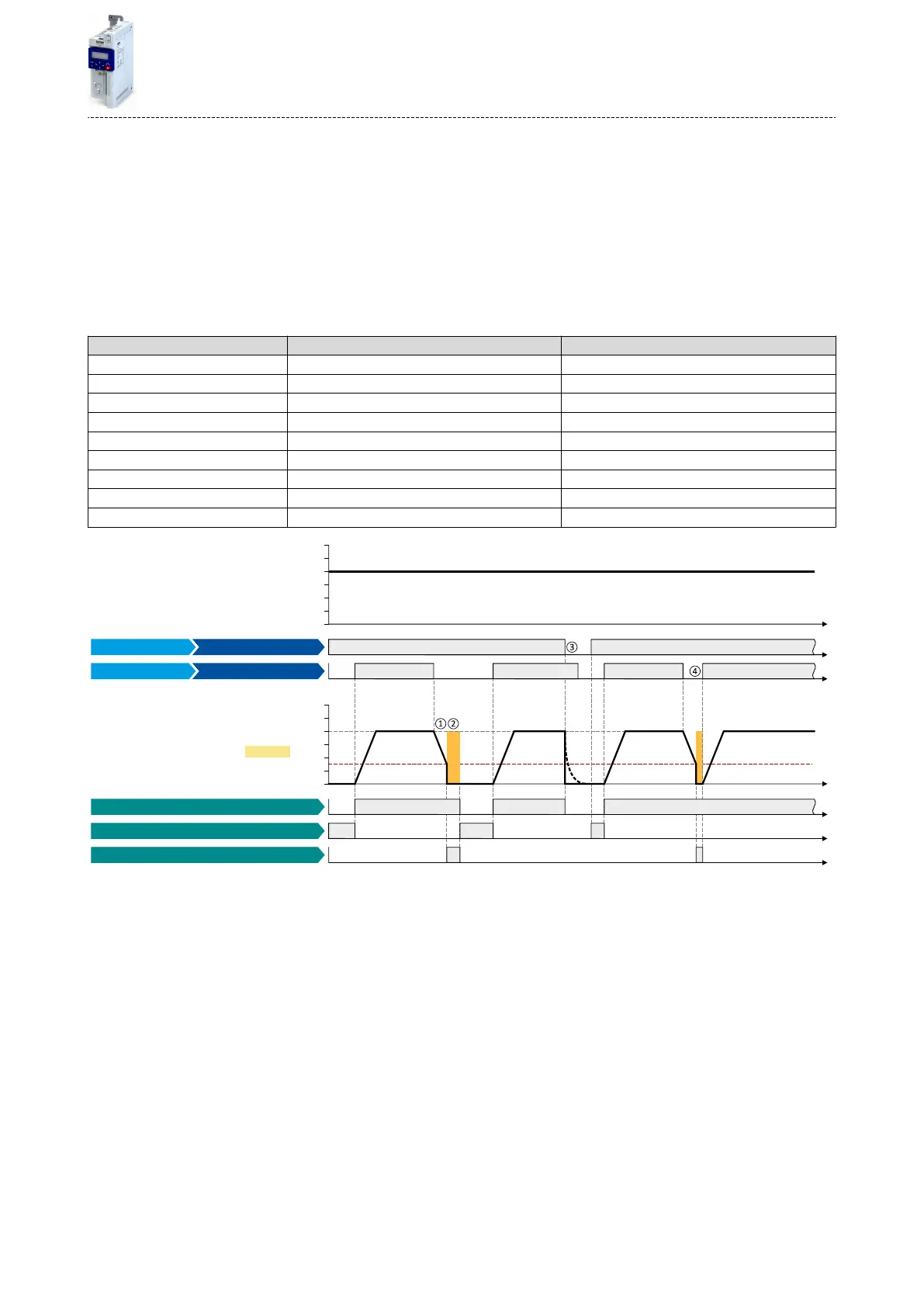
Parameter Name Seng for this example
0x2631:001 (P400.01) Enable inverter Digital input 1 [11]
0x2631:002 (P400.02) Run Digital input 2 [12]
0x2631:004 (P400.04) Reset fault Not connected [0]
0x2838:003 (P203.03) Stop method Standard ramp [1]
0x2860:001 (P201.01) Frequency control: Default setpoint source Frequency preset 1 [11]
0x2911:001 (P450.01) Frequency setpoint presets: Preset 1 40 Hz
0x2B84:001 (P704.01) Current 50 %
0x2B84:002 (P704.02) Automac hold me 10 s
0x2B84:003 (P704.03) Automac operang threshold 15 Hz
t
0 Hz
30 Hz
10 Hz
20 Hz
40 Hz
50 Hz
60 Hz
t
t
0 Hz
30 Hz
10 Hz
20 Hz
40 Hz
50 Hz
60 Hz
t
t
t
t
0x2DDD
Output frequency
Stop active [53]
DC braking active [67]
Running [50]
Status signals
DC brake
Digital input 2 [12] Run
Digital input 1 [11]
Output signals
Enable inverter
Input signals
Frequency setpoint selection
FunctionTrigger
The status signals can be assigned to digital outputs. 4Conguraon of digital outputs ^ 415
①
With the stop method "Standard ramp [1]", the motor is rst decelerated normally unl the value falls below the operang threshold set in
0x2B84:003 (P704.03).
②
The DC braking becomes acve for the hold me set in 0x2B84:002 (P704.02).
③
If the inverter is disabled, the motor coasts. (DC braking is only possible if the inverter is enabled.)
④
If there is a new start command within the hold me, the DC braking is cancelled. The motor is accelerated to the setpoint again.
Stop method = "Quick stop ramp [2]"
Same behaviour as with the stop method "Standard ramp [1]", except that the motor is decel-
erated with the quick stop ramp instead of the standard ramp.
Addional funcons
DC braking
Example 2: Automac DC braking when the motor is stopped
271

 Loading...


