EasyManuals Logo

Lenze i510 Series Commissioning

Lenze i510 Series
487 pages
To Next Page IconTo Next Page
To Previous Page IconTo Previous Page
Page #437 background imageLoading...
Page #437 background image
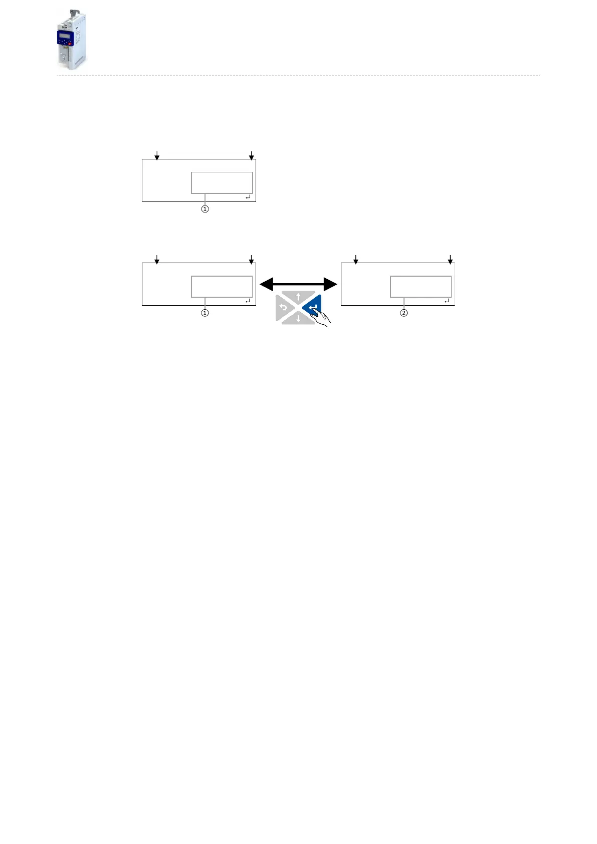
15.1.2.4 Display of status words on keypad
Some diagnoscs parameters contain bit-coded status words. Each single bit has a certain
meaning.
Display of 16-bit status words on the keypad
MAN AUTO SETLOC REM
b.0000.0000.0000.0100
0 0 x o O O 4
Bit 15 Bit 0
Hexadecimal value
Display of 32-bit status words on the keypad
MAN AUTO SETLOC REM
b.0000.0000.0000.0001
H W X o O O 1
Bit 31 Bit 16
MAN AUTO SETLOC REM
b.0000.0000.0000.0000
L W X o O O O
Bit 15 Bit 0
Hexadecimal value High word (HW)
Hexadecimal value Low word (LW)
Appendix
Operate and parameterise the inverter with keypad
Keypad parameterisaon mode
437

Table of Contents

Other manuals for Lenze i510 Series

Questions and Answers:

Question and Answer IconNeed help?

Do you have a question about the Lenze i510 Series and is the answer not in the manual?

Lenze i510 Series Specifications

General IconGeneral
Protection ClassIP20
Overload Capacity150% for 60 seconds
Enclosure RatingIP20
DimensionsVaries by model
WeightVaries by model
Control TypeV/f control, vector control
Communication InterfacesCANopen, Modbus RTU, EtherCAT, PROFIBUS, PROFINET
Ambient Temperature-10°C to +50°C
Braking ResistorOptional
SafetySTO (Safe Torque Off)
Protection FeaturesOvercurrent, overvoltage, undervoltage, overtemperature, short circuit
Output Voltage0 to input voltage
Input Voltage200-240 V, 380-480 V
Voltage Range200-240 V, 380-480 V
Frequency Range0 to 599 Hz

Related product manuals