13.4 Reset error
By means of the "Reset fault" funcon, an acve error can be reset (acknowledged).
Precondions
The error can only be reset if the error cause has been eliminated.
Parameter Name / value range / [default seng] Info
0x2631:004
(P400.04)
Funcon list: Reset fault
(Funcon list: Reset fault)
•
For further possible sengs, see parameter
0x2631:001 (P400.01). ^ 351
Assignment of a trigger for the "Reset fault" funcon.
Trigger = FALSE↗TRUE (edge): Acve error is reset (acknowledged) if the
error condion is not acve anymore and the error is reseable.
Trigger = FALSE: no acon.
12 Digital input 2
0x2839:006 Fault conguraon: Fault handling in case of state
change
Selecon whether a pending error is to be reset via the funcons "Ena-
ble inverter" 0x2631:001 (P400.01) and "Run" 0x2631:002 (P400.02) as
well.
0 Reset fault
1 Do not reset fault
Further opons for reseng an error
In addion to the "Reset error" funcon, there are the following opons to reset an error:
funcon Required state change to reset an error:
Enable inverter 0x2631:001 (P400.01) TRUE↘FALSE (edge)
Run 0x2631:002 (P400.02) TRUE↘FALSE (edge); see the following example
Keypad key
Keystroke
Example for operang mode
•
Switch S1 starts the motor in forward direcon of rotaon. Switch S1 in the inial posion
stops the motor again.
•
Switch S2 resets the current error if the error condion is not acve anymore and the error
is reseable.
•
The switches/sensors S3 and S4 serve to set the inverter from the process to the error sta-
tus. 4Triggering a user-dened fault ^ 392
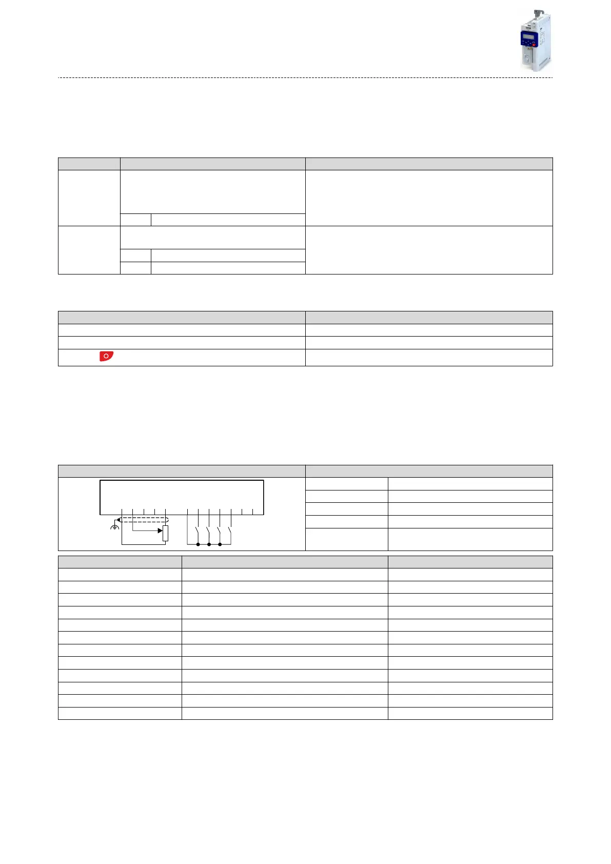
Connecon plan funcon
GND
AI1
AI2
AO1
10V
24V
DI1
DI2
DI3
DI4
DI5
DO1
X3
S1 S2 S3 S4
1k ...10k
0 ... 10 V
R1
Potenometer R1 Frequency setpoint selecon
Switch S1 Run
Switch S2 Reset fault
Switch S3 Acvate fault 1
Switch S4 Acvate fault 2
Parameter Name Seng for this example
0x2631:001 (P400.01) Enable inverter Constant TRUE [1]
0x2631:002 (P400.02) Run Digital input 1 [11]
0x2631:004 (P400.04) Reset fault Digital input 2 [12]
0x2631:013 (P400.13) Reverse rotaonal direcon Not connected [0]
0x2631:018 (P400.18) Acvate preset (bit 0) Not connected [0]
0x2631:043 (P400.43) Acvate fault 1 Digital input 3 [13]
0x2631:044 (P400.44) Acvate fault 2 Digital input 4 [14]
0x2824 (P200.00) Control selecon Flexible I/O conguraon [0]
0x2838:003 (P203.03) Stop method Standard ramp [1]
0x2860:001 (P201.01) Frequency control: Default setpoint source Analog input 1 [2]
0x2918 (P221.00) Deceleraon me 1 5.0 s
0x291C (P225.00) Quick stop deceleraon me 1.0 s
Flexible I/O conguraon
Reset error
384

 Loading...


