13.14 Conguraon of analog inputs
13.14.1 Analog input 1
Sengs for analog input 1.
Details
The analog input 1 can be used as setpoint source.4Selecon of setpoint source ^ 98
For the process controller, the analog input can be used for the feedback of the variable
(actual value) or speed feedforward control. 4Basic process controller sengs ^ 239
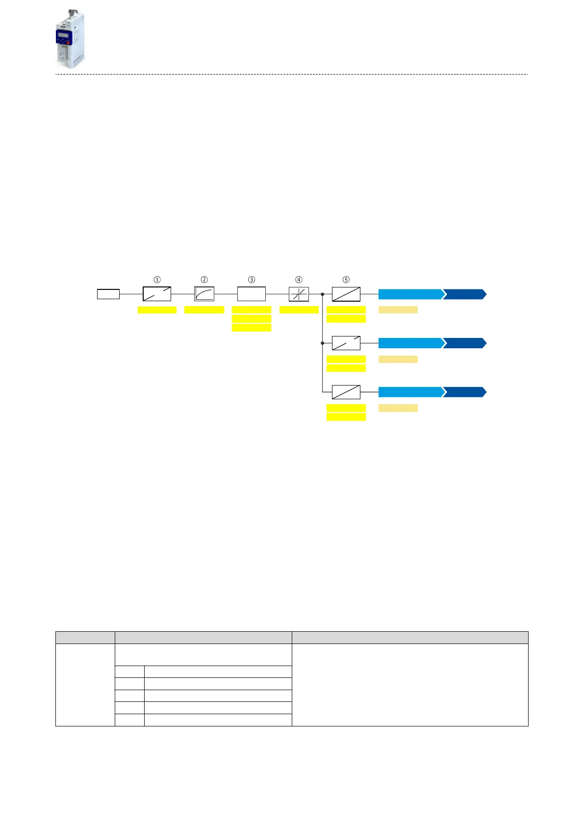
The following sengs are possible for the analog input:
•
Denion of the input range
①
•
Filter me for low-pass lters
②
•
Monitoring of the input signal
③
•
Dead band for eliminang the smallest signal levels
④
•
Denion of the seng range
⑤
AI1
0x2636:0020x2636:0080x2636:001
%
Hz
0x2636:006
0x2636:0030x2636:009
0x2636:010
0x2636:007
0x2636:004
0x2636:005
%
PID
X3
%
V/mA
0x2DA4:002
0x2DA4:003
x y
<
>
0x2860:001
0x2860:002
[Hz]
[PID unit]
0x2636:011
0x2636:012
%
%
0x2DA4:004
0x2860:003
[%]
unit
Analog input 1 [2]
Torque setpoint source
Analog input 1 [2]
Process controller setpoint source
Frequency setpoint source
Analog input 1 [2]
Diagnosc parameters:
•
The frequency value is displayed in 0x2DA4:002 (P110.02).
•
The process controller value is displayed in 0x2DA4:003 (P110.03).
•
The torque value is displayed in 0x2DA4:004 (P110.04).
Denion of the input range
The analog input can be congured as voltage or current input. Internally, the signal is always
converted to a value in percent.
Denion of the seng range
The seng range results from the set min and max value for the respecve mode.
Conguraon examples
Detailed conguraon examples can be found in the following subchapters:
4Example 1: Input range 0 ... 10 V ≡ seng range 0 ... 50 Hz ^ 411
4Example 2: Input range 0 ... 10 V ≡ seng range -40 ... +40 Hz ^ 411
4Example 3: Error detecon ^ 412
Parameter Name / value range / [default seng] Info
0x2636:001
(P430.01)
Analog input 1: Input range
(Analog input 1: AI1 input range)
Denion of the input range.
0 0 ... 10 VDC
1 0 ... 5 VDC
2 2 ... 10 VDC
4 4 ... 20 mA
5 0 ... 20 mA
Flexible I/O conguraon
Conguraon of analog inputs
Analog input 1
409

 Loading...


