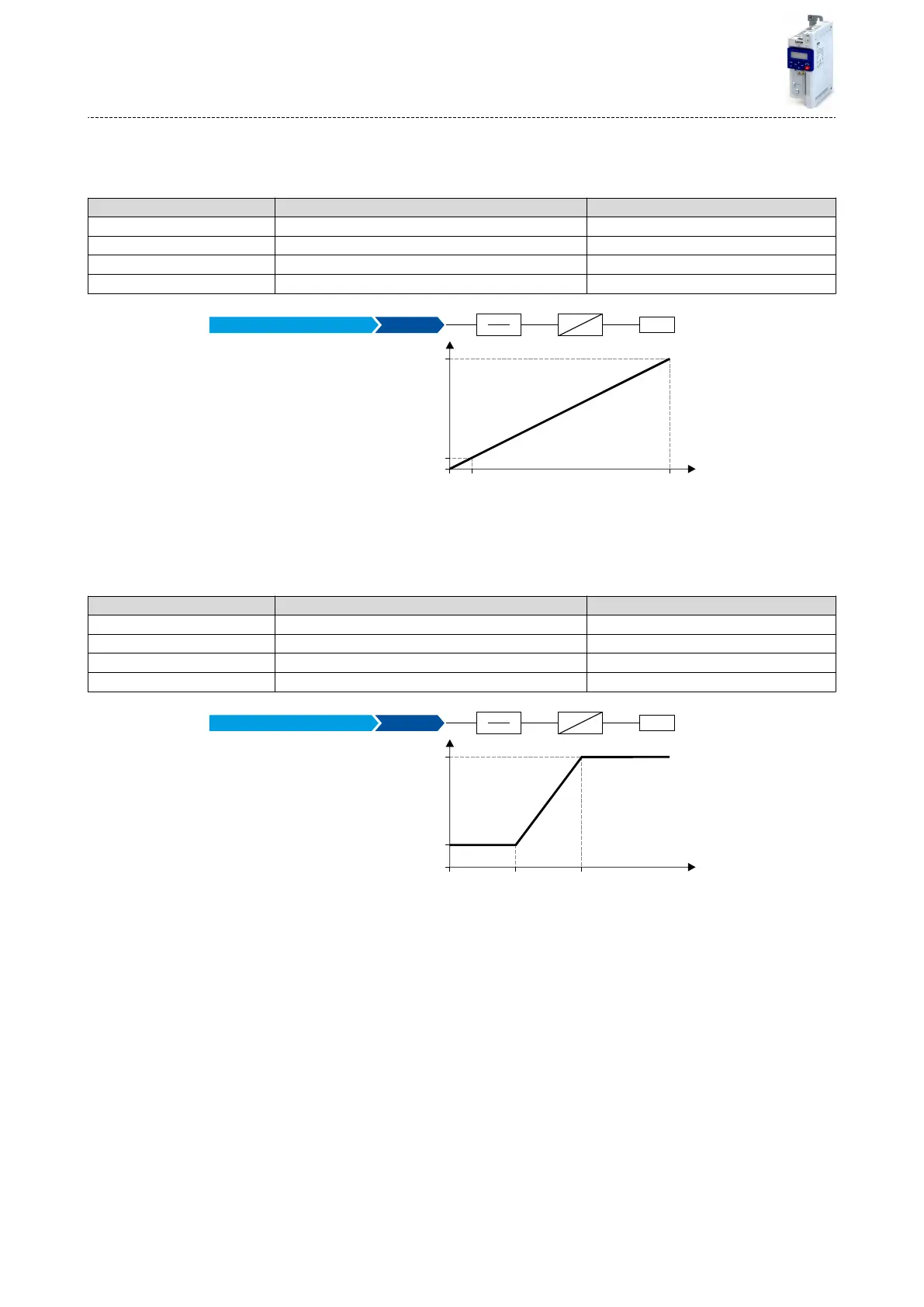
13.16.1.1 Example 1: Output voltage 0 ... 10 V ≡ output frequency 0 ... 100 Hz
In this conguraon, a voltage is provided at the analog output proporonately to the current
output frequency of the inverter (1 V ≡ 10 Hz, resoluon 0.1 Hz).
Parameter Name Seng for this example
0x2639:001 (P440.01) Analog output 1: Output range 0 ... 10 VDC [1]
0x2639:002 (P440.02) Analog output 1: Funcon Output frequency [1]
0x2639:003 (P440.03) Analog output 1: Min. signal 0
0x2639:004 (P440.04) Analog output 1: Max. signal 1000
1000
0
10
[V]
[0.1 Hz]0
100.0
[Hz]
1
100
10.0
AO1
X3
V
0x2639:002
Min
Max
Output frequency [1]
13.16.1.2 Example 2: Output voltage 2 ... 10 V ≡ output frequency 30 ... 60 Hz
In this conguraon, the output range 2 ... 10 V is used for the output of the output frequency
(resoluon: 0.1 Hz). The example shows how the signals outside the signal range (here:
30 ... 60 Hz) are cut o.
Parameter Name Seng for this example
0x2639:001 (P440.01) Analog output 1: Output range 2 ... 10 VDC [3]
0x2639:002 (P440.02) Analog output 1: Funcon Output frequency [1]
0x2639:003 (P440.03) Analog output 1: Min. signal 300
0x2639:004 (P440.04) Analog output 1: Max. signal 600
0
10
[V]
[0.1 Hz]0
60.0
[Hz]30.0
AO1
X3
V
0x2639:002
Min
Max
2
600300
Output frequency [1]
Flexible I/O conguraon
Conguraon of analog outputs
Analog output 1
424
 Loading...


