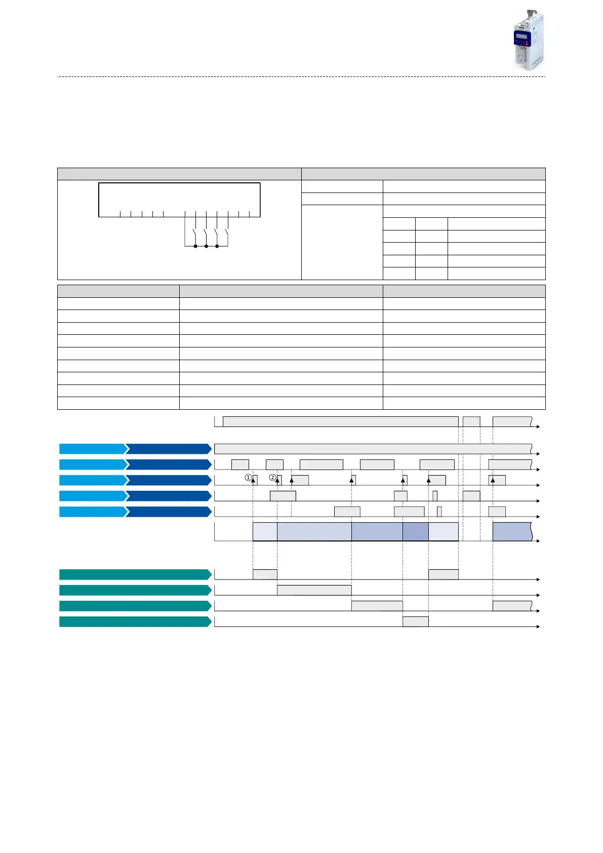
13.9.2 Example 2: Acvaon via command (immediately)
Acvaon method 0x4046 (P755.00) = "Via command (immediately) [1]":
•
Switches S3 and S4 serve to select the parameter set (see the following table).
•
Switch S2 acvates the change-over. Since the change-over is acvated with a rising edge,
a buon (normally-open contact) can be used instead of a switch.
•
Change-over takes place immediately, even if the motor is started (switch S1 closed).
Connecon plan funcon
GND
AI1
AI2
AO1
10V
24V
DI1
DI2
DI3
DI4
DI5
DO1
X3
S1 S2 S3 S4
Switch S1 Run
Switch S2 Load parameter set
Switches S3 ... S4 Parameter set selecon:
S3 S4
O O Parameter set 1
On O Parameter set 2
O On Parameter set 3
On On Parameter set 4
Parameter Name Seng for this example
0x2631:001 (P400.01) Enable inverter Constant TRUE [1]
0x2631:002 (P400.02) Run Digital input 1 [11]
0x2631:004 (P400.04) Reset fault Not connected [0]
0x2631:018 (P400.18) Acvate preset (bit 0) Not connected [0]
0x2631:040 (P400.40) Load parameter set Digital input 2 [12]
0x2631:041 (P400.41) Select parameter set (bit 0) Digital input 3 [13]
0x2631:042 (P400.42) Select parameter set (bit 1) Digital input 4 [14]
0x2824 (P200.00) Control selecon Flexible I/O conguraon [0]
0x4046 (P755.00) Acvaon of parameter set Via command (immediately) [1]
t
t
t
t
t
t
t
t
t
t
t
1
2
3 4 31
RunDigital input 1 [11]
Select par. set (bit 0)
Enable inverter
Select par. set (bit 1)Digital input 4 [14]
Constant TRUE [1]
Digital input 3 [13]
Digital input 2 [12]
Mains voltage
Parameter set 4 active [111]
Parameter set 1 active [108]
Parameter set 3 active [110]
Parameter set 2 active [109]
Output signals
Status signals
Active parameter set
Load parameter set
Input signals
FunctionTrigger
The status signals can be assigned to digital outputs. 4Conguraon of digital outputs ^ 415
①
The change-over is acvated with the "Load parameter set" funcon (FALSE/TRUE edge).
②
Change-over is also possible if the inverter is enabled and the motor is started.
Flexible I/O conguraon
Funcons for parameter change-over
Example 2: Acvaon via command (immediately)
396

 Loading...


