Source logic
+24
DI1 to DI7
DIC
Output unit Inverter
Photocoupler
Sink
Source
24 VDC
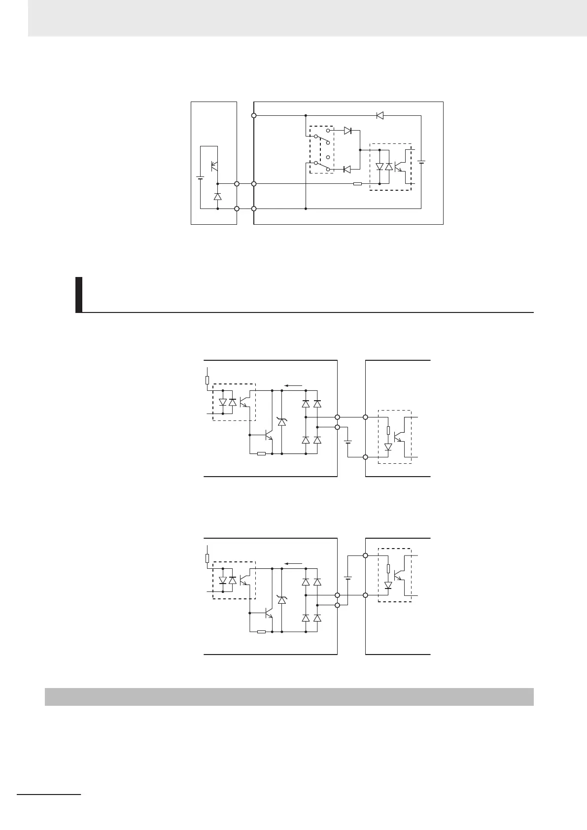
Multifunction Output Terminals and Programmable Controller Con-
nection
Sink logic
55 to
70 V
DOC
DO1
Input unitInverter
Photocoupler
Sink input
Current flow
24 VDC
Source logic
55 to
70 V
DOC
DO1
Input unitInverter
Photocoupler
Source input
Current flow
24 VDC
2-3-6
Recommended Encoder and Its Wiring
For the pulse train input function of the 3G3M1 Series inverter, be sure to use a complementary output
type encoder.
In addition, for encoder cable connection, always use a shielded cable and connect it to the DIC termi-
nal of the inverter
’s control circuit terminal block.
2 Design
2-62
M1 Series EtherCAT Type User’s Manual (I670)
 Loading...


