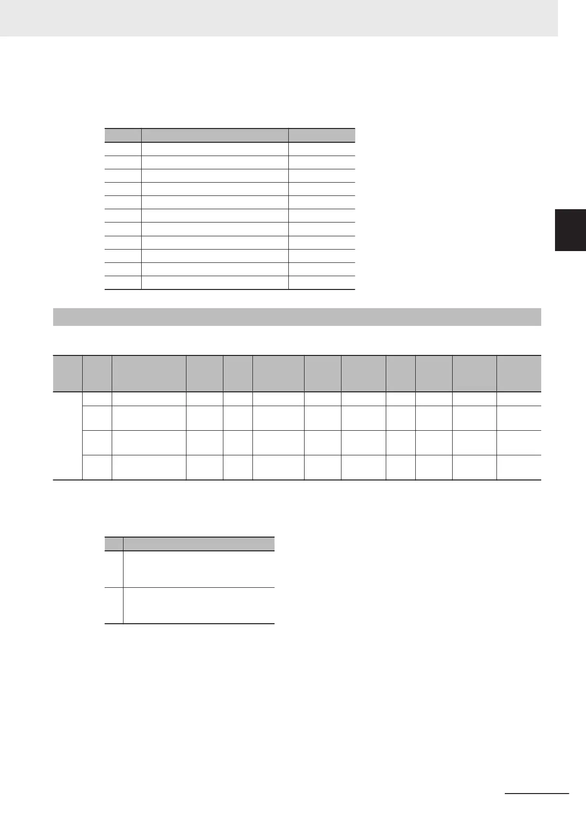
• This object gives the supported modes of operation.
• Bit Descriptions
Bit Supported mode Value
0 pp (Profile position mode) 0: Not supported
1 vl (Velocity mode) 1: Supported
2 pv (Profile velocity mode) 0: Not supported
3 tq (Profile torque mode) 0: Not supported
4 Reserved 0: Not supported
5 hm (Homing mode) 0: Not supported
6 ip (Interpolated position mode) 0: Not supported
7 csp (Cyclic synchronous position mode) 0: Not supported
8 csv (Cyclic synchronous velocity mode) 0: Not supported
9 cst (Cyclic synchronous torque mode) 0: Not supported
10 to 31 Reserved 0: Not supported
A-2-9
Safety Function Objects
This section explains objects defined in the FSoE CiA402 slave connection.
Index
(hex)
Sub-
index
(hex)
Object name
Setting
range
Unit
Default set-
ting
Data
attrib-
ute
Size
Ac-
cess
PDO
map
Complete
access
Modes of
operation
6620 --- safety controlword --- --- --- --- --- --- --- Possible ---
00 Number of entries --- --- 02 hex --- 1 byte
(U8)
RO --- --- ---
01 safety controlword
1st Byte
--- --- --- --- 1 byte
(U8)
RO --- --- ---
02 safety controlword
2nd Byte
--- --- --- --- 1 byte
(U8)
RO --- --- ---
• This object gives the command status of the safety function.
• Bit Description of Subindex 01 hex
Bit Description
0 Gives the status of STO command.
0: ST
O activate command issued
1: ST
O activate command not issued
7 Gives the status of error reset command.
0: Error reset command not issued
1: Error reset command issued
• No bit of subindex 02 hex is used.
Appendices
A-35
M1 Series EtherCAT Type User’s Manual (I670)
A-2 CoE Objects
A
A-2-9 Safety Function Objects
 Loading...


