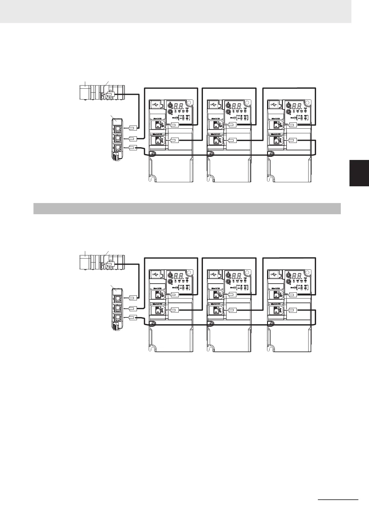
ECAT OUT connector on the last inverter to the X3 connector (end port of the ring) on the EtherCAT
Junction Slave.
Inverter A
Power supply unit NJ/NX-series CPU Unit
IN
X2
X3
EtherCAT
Junction Slave
Inverter B Inverter C
3-9-3
Procedure of Checking Operation
This section takes the following configuration example and describes how to check that the cable re-
dundancy function operates correctly
.
Inverter A
Power supply unit NJ/NX-series CPU Unit
IN
X2
X3
EtherCAT
Junction Slave
Inverter B Inverter C
1 Check that the devices start up in the normal status.
• Connect the EtherCA
T communications cables correctly, and turn ON the power supply to
the EtherCAT master and to the slaves.
• Check that there is no problem with the EtherCAT master and the slaves.
• Check that the L/A IN indicators and the L/A OUT indicators of all slaves blink.
• Turn OFF the power supply to the EtherCAT master and to the slaves.
2 With a cable disconnected from a connector, check that the communications continue in the
ring disconnection status.
• Disconnect the cable from the ECA
T IN connector on "Inverter B", and protect the discon-
nected cable connector.
• Turn ON the power supply to the EtherCAT master and to the slaves.
• Check that there is no problem with the EtherCAT master and the slaves.
3 EtherCAT Communications
3-17
M1 Series EtherCAT Type User’s Manual (I670)
3-9 Cable Redundancy Function
3
3-9-3 Procedure of Checking Operation
 Loading...


