Parameter Value Standard
SIL 3
EN/IEC 61508-1 to -7
EN/IEC 61800-5-2
EN/IEC 62061
HFT 1
SFF >90%
STO Function by
Safe Input Signal
PFH
3.00 × 10
-9
PFD
4.00 × 10
-5
Mission time 20 years
STO Function via
EtherCA
T Com-
munications
PFH
1.10 × 10
-8
PFD
1.10 × 10
-4
Mission time
10 years
8-6-2
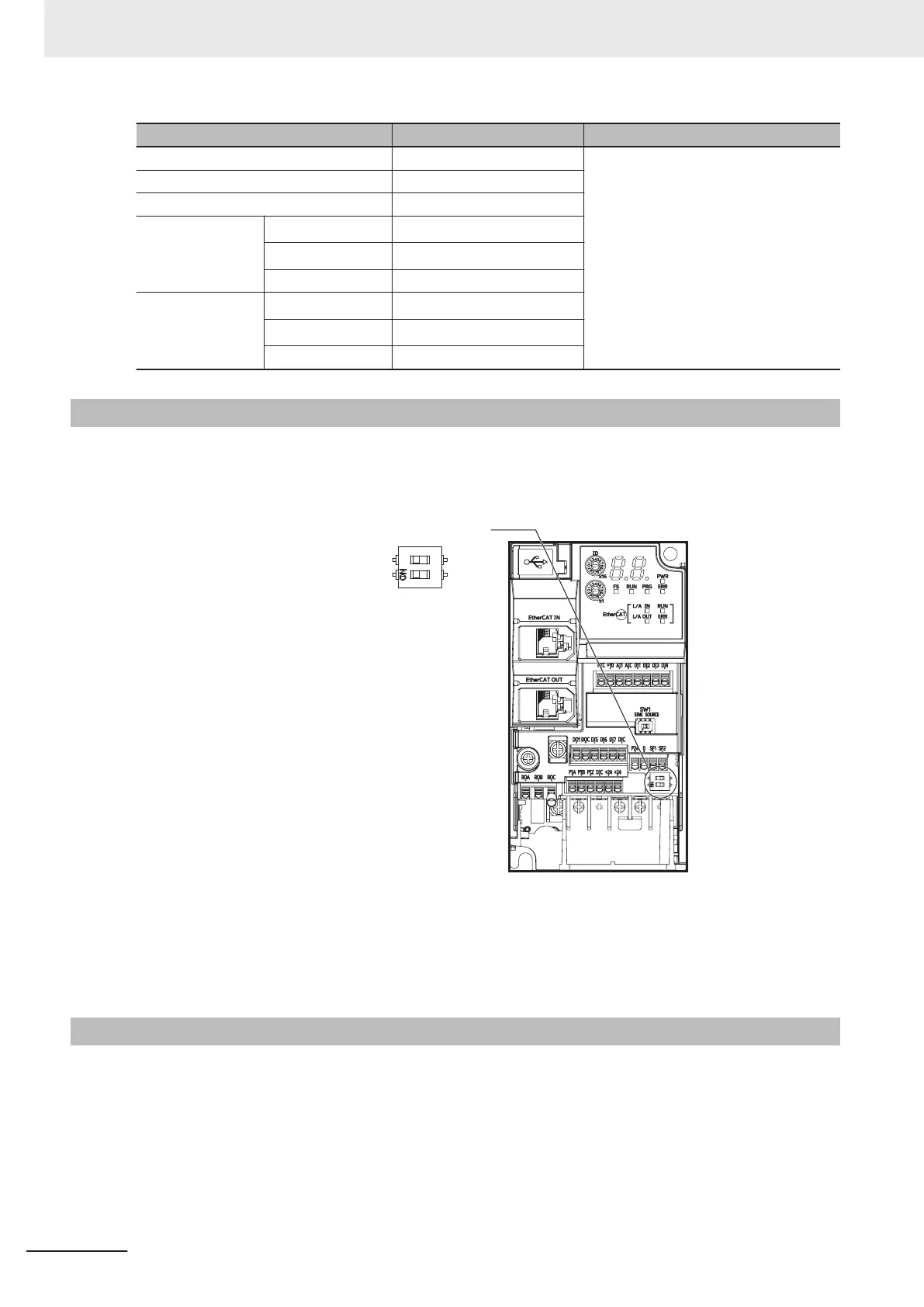
Safety Function Settings
Turn OFF the safety function selector switch SW9 when the inverter power supply is turned OFF.
Set SW9 to enabled (OFF) or disabled (ON) so that both sides are at the same position at all times.
Safety function selector switch
ON
(Safety function
disabled)
OFF
Turn both OFF to use the safety function.
Turn both ON to not use the safety function.
When only one is ON, the logic of the SF1 and SF2 signals no longer matches and this causes an EN
circuit failure (alarm code: 39).
8-6-3
STO Function by Safety Input Signal
The safety input function allows the inverter output when current flows in both the terminals [SF1] and
[SF2]. When the safety input function is activated, in compliance with the safety standards described
in 8-6-1 Overview of Safety Function on page
8-61, the output transistor operation of the inverter is
stopped safely (by shutting off its output). As a result, the motor stops with free run.
• It takes 50 ms or shorter from when the safety input is input till when the inverter shuts off the out-
put.
• St is displayed on the data display.
8 Other Functions
8-62
M1 Series EtherCAT Type User’s Manual (I670)
 Loading...


