3-9
Cable Redundancy Function
Configuring a ring topology on the EtherCAT system enables communications to continue even if an
EtherCAT physical layer link is disconnected in the ring topology.
Possible causes for the ring disconnection status in which an EtherCAT physical layer link is discon-
nected are as follows:
• An EtherCAT communications cable is disconnected, loose, broken, or short-circuited.
• Failure in the EtherCAT physical layer of an EtherCAT inverter
3-9-1
Description of Operation
This function enables communications to continue even if a cable is disconnected or broken in a ring
topology and the ring disconnection status results.
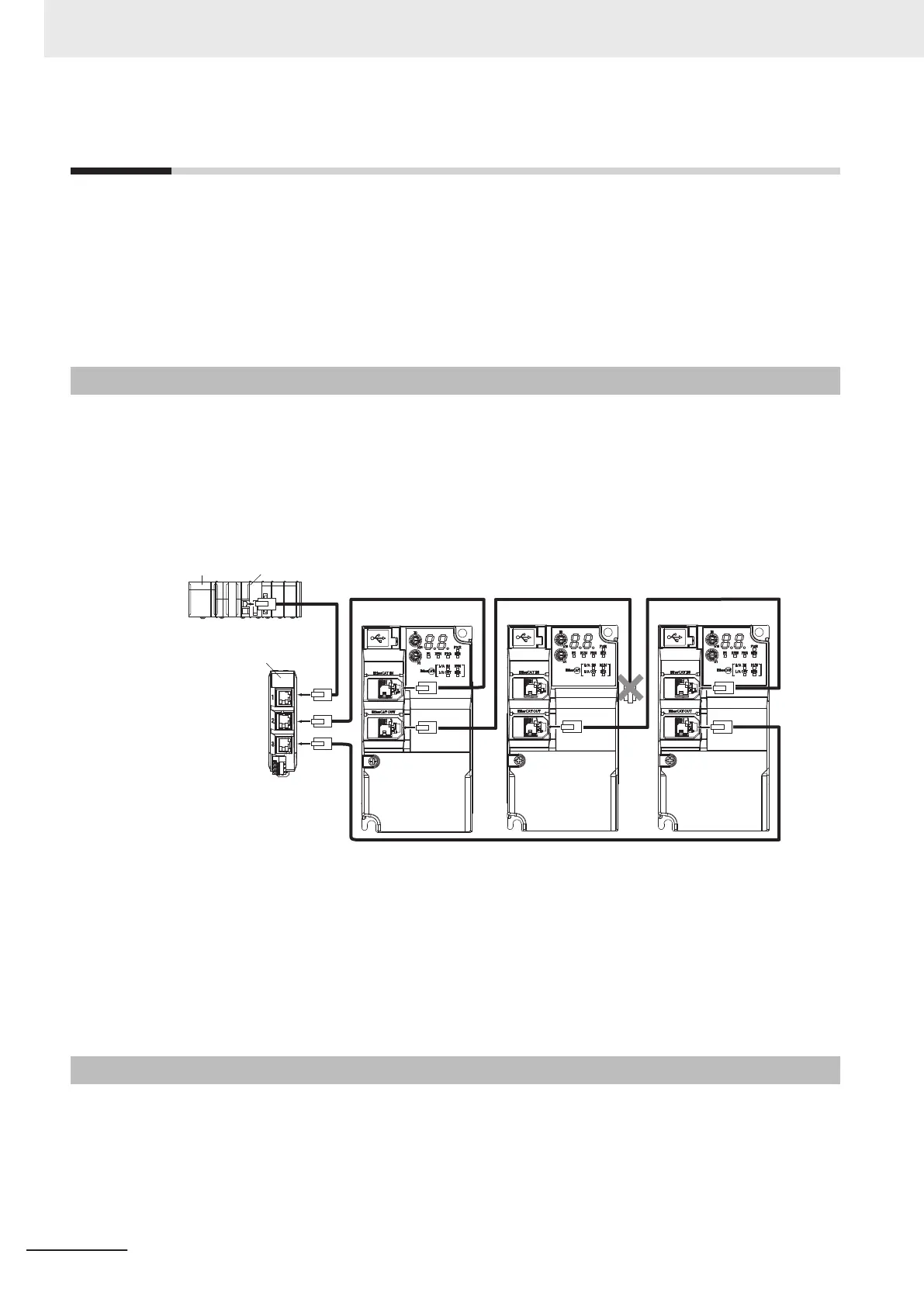
Even when the cable is disconnected from the ECAT IN connector on the EtherCAT inverter B and the
ring disconnection status results as in the figure below, all EtherCAT inverters can continue communi-
cations. If an EtherCAT communications cable is disconnected, protect the conductor so that the dis-
connected connector does not touch the control panel or other equipment.
IN
X2
X3
Inverter A
Power supply unit
NJ/NX-series CPU Unit
EtherCAT
Junction Slave
Inverter B Inverter C
The ring disconnection status may have resulted from a broken or short-circuited communications ca-
ble or an inverter failure, instead of EtherCAT communications cable disconnection. If the ring discon-
nection status occurs, immediately perform inspection and take appropriate measures. Refer to
10-1-8 Method for Ring Disconnection Maintenance and Inspection on page 10-
9 for details on the
inspection method.
If the ring disconnection status occurs due to a broken or short-circuited communications cable or an
inverter failure, continuing to use the devices as they are may stop the entire communications system.
3-9-2
Wiring
This example shows how to connect an NJ/NX-series CPU Unit to inverters via an OMRON GX-JC03
EtherCAT Junction Slave by the use of EtherCA
T Communications Cables. Connect the NJ/NX-series
CPU unit to the IN connector on the EtherCAT Junction Slave. Connect the X2 connector (start port of
the ring) on the EtherCAT Junction Slave to the ECAT IN connector on the first inverter. Connect the
ECAT OUT connector on the first inverter to the ECAT IN connector on the next inverter. Connect the
3 EtherCAT Communications
3-16
M1 Series EtherCAT Type User’s Manual (I670)
 Loading...


