4-3
Control with the CiA402 Profile
This section describes how to use the Velocity mode of the CiA402 drive profile to control the inverter.
4-3-1
Inverter Setting
The inverter parameters must be set to match the profile.
With the CiA402 profile, set as follows.
Index-Subindex Parameter Description
3004-02 hex 1st Frequency Reference Selection 15: EtherCAT (Default setting)
3004-03 hex 1st RUN Command Selection 5: EtherCAT (Default setting)
3007-02 hex 1st Motor Pole Number 2 to 128 (Default setting: 4)
(Set to match the system.)
4-3-2
Profile Allocation
Assign the PDOs of the CiA402 profile to Sync Manager.
Sync Manager PDO assignment Description
1C12 hex 1700 hex (Fixed allocation conforming to the CiA402 drive profile)
1C13 hex 1B00 hex (Fixed allocation conforming to the CiA402 drive profile)
The values below are the fixed mapping for the PDOs.
PDO Description
1700 hex 6040 hex (Controlword)
6042 hex (vl target velocity)
1B00 hex 6041 hex (Statusword)
6043 hex (vl velocity demand)
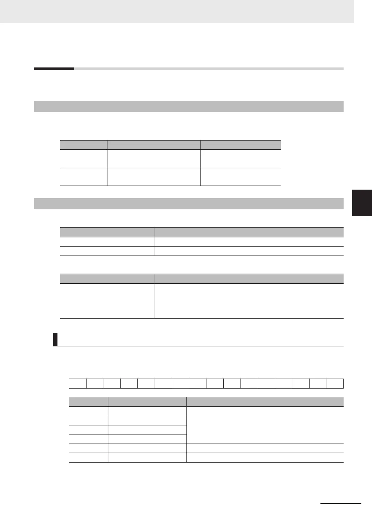
Bit and Data Information
Controlword
The 16-bit data is as shown below.
− − − − − − − − 7 − − − 3 2 1 0
Bit Name Meaning
0 Switch on The state is controlled by these bits.
For details, refer to State Control Commands on page A-4
.
1
Enable voltage
2 Quick stop
3 Enable operation
7 Fault reset Faults and warnings are cleared when this bit turns ON.
− Reserved Set 0.
4 Inverter Control
4-7
M1 Series EtherCAT Type User’s Manual (I670)
4-3 Control with the CiA402 Profile
4
4-3-1 Inverter Setting
 Loading...


