4-2
Control with the Independent Profile
This section describes how to use the OMRON profile to control the inverter.
4-2-1
Inverter Setting
The inverter parameters must be set to match the profile.
With the independent profile, set as follows.
Index-Subindex Parameter Description
3004-02 hex 1st Frequency Reference Selection 15: EtherCAT (Default setting)
3004-03 hex 1st RUN Command Selection 5: EtherCAT (Default setting)
4-2-2
Profile Allocation
Assign the PDOs of the independent profile to Sync Manager.
Sync Manager PDO assignment Description
1C12 hex 1701 hex (Fixed allocation of the independent profile)
1C13 hex 1B01 hex (Fixed allocation of the independent profile)
The values below are the fixed mapping for the PDOs.
PDO Description
1701 hex 5000 hex (Command)
5010 hex (Frequency Reference)
1B01 hex 5100 hex (Status)
5110 hex (Output Frequency Monitor)
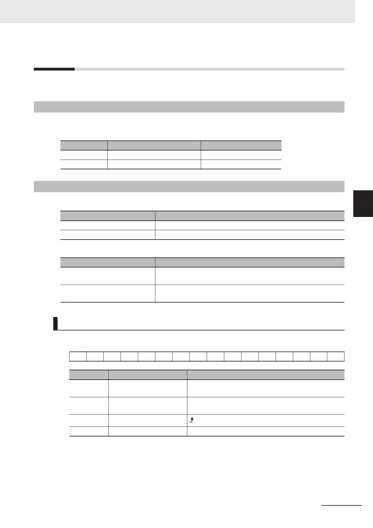
Bit and Data Information
Command
− − − − − − − − 7 − − − − − 1 0
Bit Name Meaning
0 Forward/stop 0: Stop
1: Forward command
1 Reverse/stop 0: Stop
1: Reverse command
7 Fault reset
: Resets an error or trip for the inverter.
− Reserved Set 0.
4 Inverter Control
4-5
M1 Series EtherCAT Type User’s Manual (I670)
4-2 Control with the Independent Profile
4
4-2-1 Inverter Setting
 Loading...


