5-1
Part Names
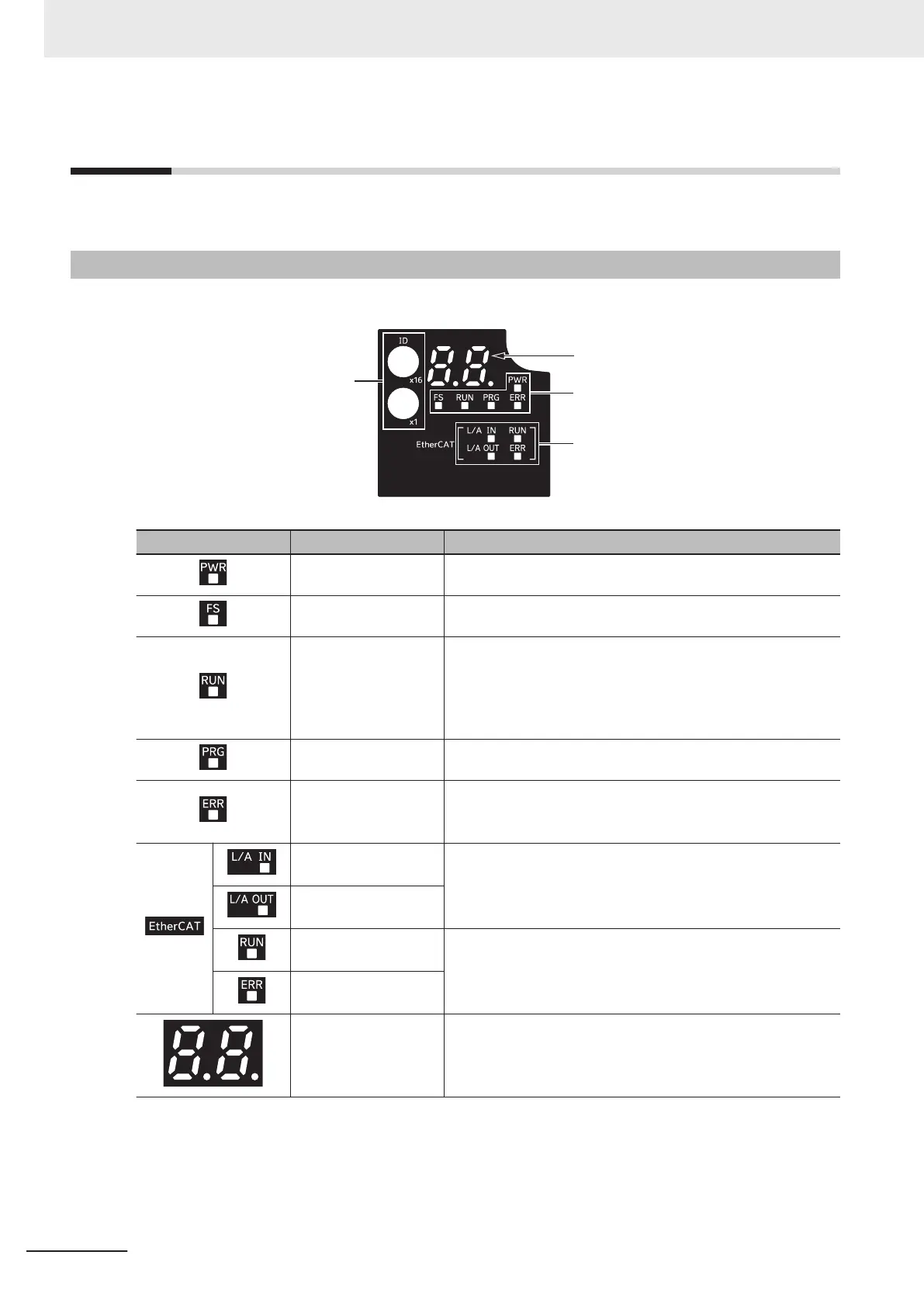
The following shows the names and descriptions of the data display and LEDs.
5-1-1
Part Names and Descriptions
The table below shows the name and function of each part.
ID switches
EtherCAT LED
Inverter status LED
Display area
Display Name Description
Power LED The control power supply status is displayed.
FS LED The safety communication status is displayed.
RUN LED Lights (green) when the inverter is running (during output to
the motor). Lights during deceleration after RUN command
OFF
. Goes out while the RUN command is ON at Frequency
Reference 0 Hz as there is no output (excluding Zero Speed
Control).
Program LED Lights when there is an error in PDO mapping.
Error LED Lights (red) when the inverter trips.
For how to reset a trip error state, refer to How to Reset a Trip
State
on page 9-2.
EtherCAT
L/A IN LED
Lights or flashes by linking of the EtherCAT physical layer.
EtherCAT
L/A OUT LED
EtherCAT
RUN LED
The EtherCAT communication status is displayed.
EtherCAT
Error LED
Data display Error display No., inverter status, etc. is displayed by a two-
digit seven-segment LED.
5 Operation and Test Run
5-2
M1 Series EtherCAT Type User’s Manual (I670)
 Loading...


