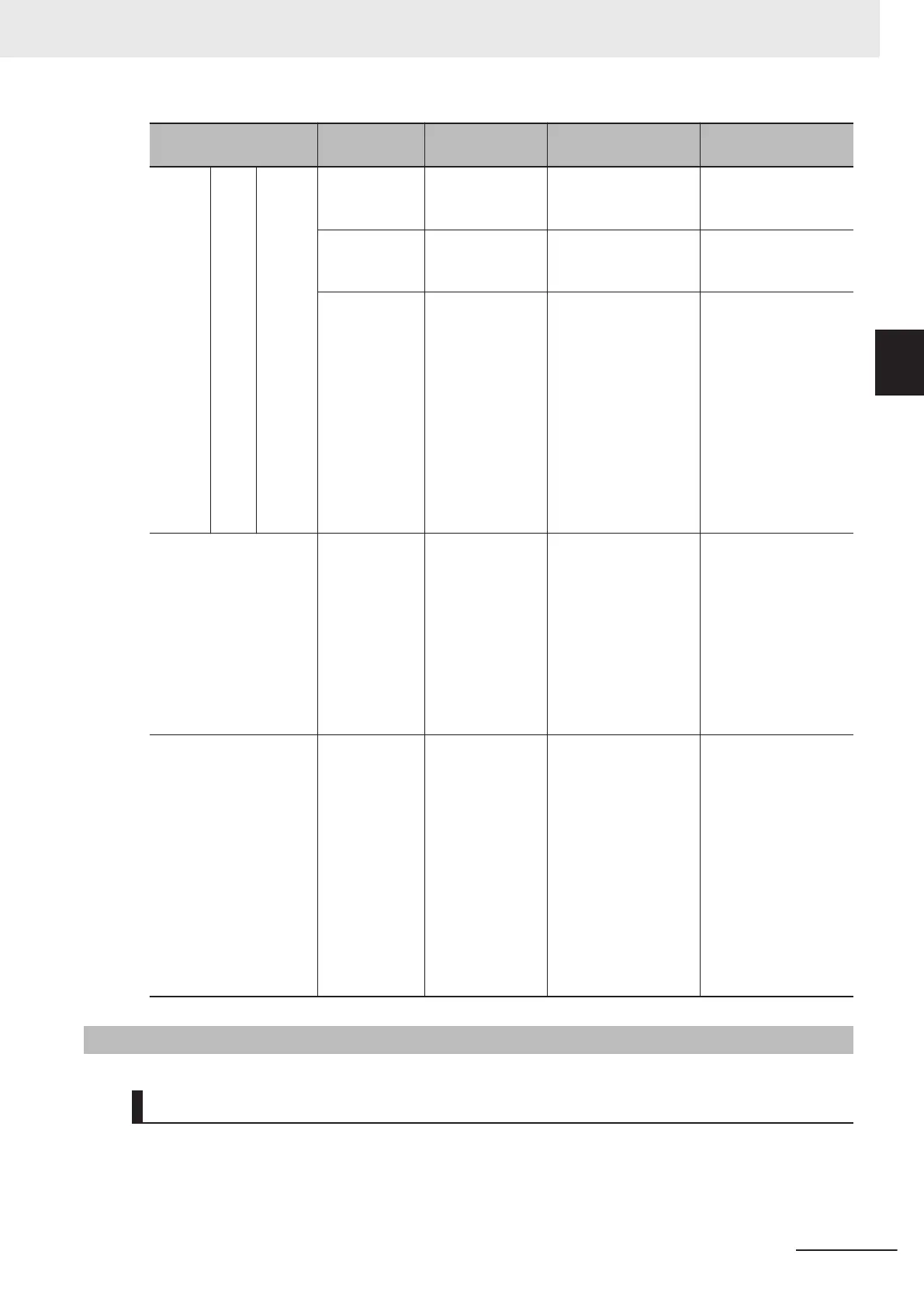
Item
Terminal sym-
bol
Terminal name Description Specifications
Digital Out-
put
Open
collec-
tor
+24 Power supply ter-
minal for output
signal
This is a 24 VDC pow-
er supply for the out-
put signal.
Allowable current:
100mA max.
DOC Output signal
common
Common terminal for
multifunction output
terminal DO1.
Allowable current: 100
mA max.
DO1 Multifunction out-
put terminal
Select functions and
allocate them to the
DO1 terminal. These
terminals support both
the sink logic and the
source logic. For de-
tails on the connec-
tion, refer to Multifunc-
tion Output T
erminals
and Programmable
Controller Connection
on page
2-62.
Open collector output
Across DO1-DOC
Allowable voltage: 48
VDC max.
Allowable current:
50mA max.
Voltage drop at pow-
er-on: 4 V max.
Multi-function relay out-
put
ROA
ROB
Relay output ter-
minal
Select the desired
function and allocate it
to these terminals.
This is SPDT contact
output.
Factory default values
are NO contact be-
tween ROA-ROC and
NC contact between
ROB-ROC.
250 VAC, 0.3 A,
cosφ=0.3/48 VDC, 0.5
A
ROC Relay output
common
24 VDC input P24
0
Auxiliary power
supply input ter-
minal
Backup power supply
for control circuit/
communication func-
tion. The P24 terminal
is insulated from the
+24 terminal.
The protection func-
tion, motor operation,
FSoE (STO), each I/O
terminal, fan, braking
transistor and inrush
current protection cir-
cuit do not operate.
24 VDC (22 to 26 V)
500 mA max.
2-3-4
Wiring for Main Circuit Terminals
Main Circuit Configuration Diagram
The diagram below shows the configuration of the inverter main circuit. The function of each peripher-
al component is also described.
2 Design
2-15
M1 Series EtherCAT Type User’s Manual (I670)
2-3 Wiring
2
2-3-4 Wiring for Main Circuit Terminals
 Loading...


