6-4
RUN command
6-4-1
RUN command selection
Select the input method for the RUN command.
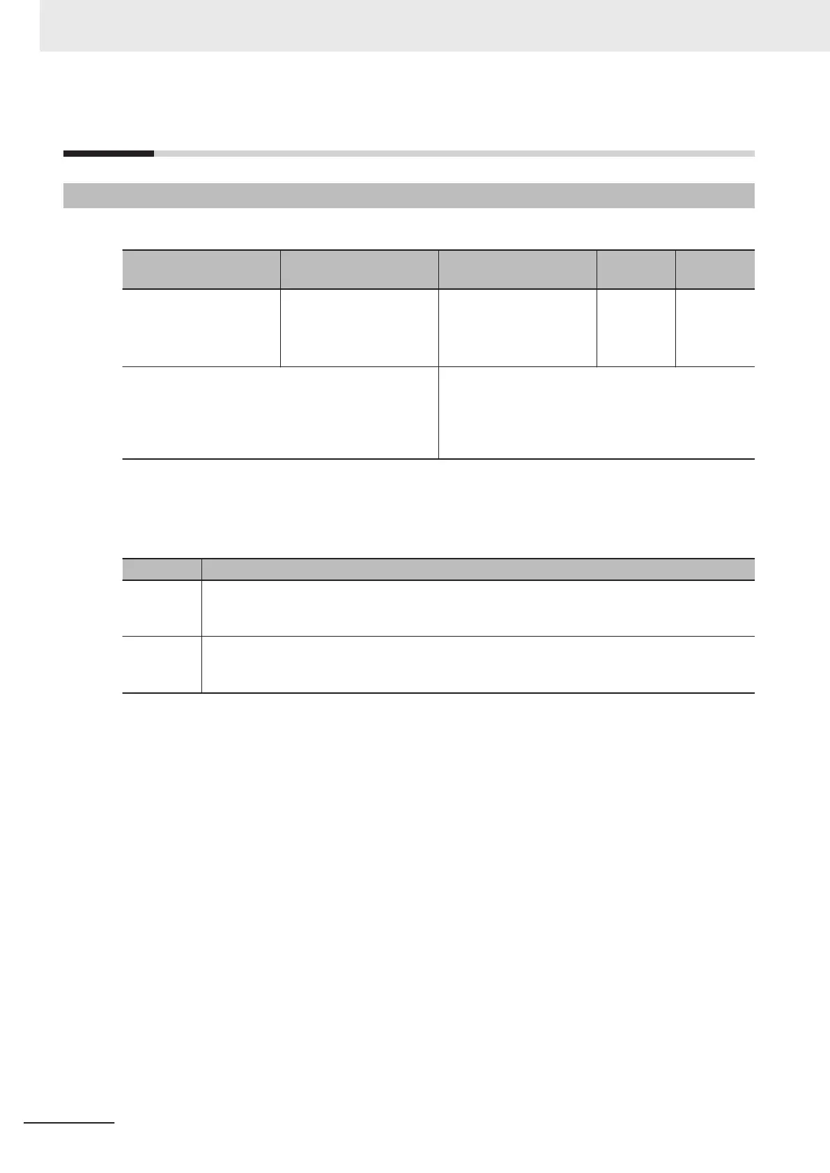
Parameter No. Function name Data
Default da-
ta
Unit
3004Hex-03Hex/
301FHex-03Hex
1st RUN Command Se-
lection
2nd RUN Command Se-
lection
*1
1: Terminal command FW
or RV
5: EtherCA
T
5 -
Related function Input Terminal [DI6] Function Selection
(3005Hex-63Hex)
Input T
erminal [DI7] Function Selection
(3005Hex-64Hex)
Operation command (3002Hex-07Hex)
*1. To enable switching to the 1st and 2nd control, allocate “12: SET (2nd control)” to either of input terminal
[DI1] to [DI7].
The operation method for data selected at 1st RUN Command Selection (3004Hex-03Hex)/2nd RUN
Command Selection (301FHex-03Hex) is as follows.
Data Operation method
1
Forward rotation is performed when the FW terminal turns ON. Reverse rotation is performed
when the RV terminal turns ON. Operation stops when both the FW and R
V terminals are OFF or
both are ON.
5
When using an unique profile, operation is instructed by 5000 hex (Reference) and when using a
CiA402 profile, it is instructed by 6040 hex (Control Word). For details, refer to S
ection 4 Inverter
Control on page 4-1.
• When “1: External signal (Digital input)” is selected at RUN Command Selection (3004Hex-03Hex/
301FHex-03Hex), allocate “98: FW (forward rotation)” and “99: RV (reverse rotation)” to each of In-
put T
erminal [DI6] Function Selection (3005Hex-63Hex) and Input Terminal [DI7] Function Selection
(3005Hex-64Hex). Operation stops when both the FW and RV terminals are ON or both are OFF.
• When “1: External signal (Digital input)” is selected at RUN Command Selection (3004Hex-03Hex/
301FHex-03Hex), 3-wire input is possible. Refer to 3-wire Input Function (FW, STP, F/R) on page
6-50.
• The RUN command from an input terminal can be forcibly enabled via input terminals. Refer to
8-6-3 STO Function by Safety Input Signal on page 8-62.
• When the inverter is outputting to the motor, operation is in progress and the RUN-LED lights. Lights
during deceleration after RUN command OFF. Goes out while the RUN command is ON at frequen-
cy reference 0 Hz as there is no output. When zero speed control is being executed, this lights as
the inverter outputs even when the frequency reference is 0 Hz.
Operation example
• The following shows an example of operation by forward command FW input and reverse com-
mand RV input when “1: External signal (Digital input)” is selected at RUN Command Selection
(3004Hex-03Hex/301FHex-03Hex).
6 Basic Settings
6-22
M1 Series EtherCAT Type User’s Manual (I670)
 Loading...


