Analog operation level at AI1Dc output can be set to any value by Analog Operation Level at [AI1] Dis-
connection (301FHex-40Hex). When set to 999, the analog input value will be used as is.
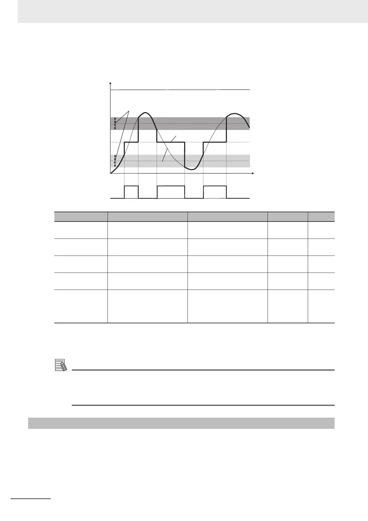
Analog command value
Max. (100%)
AI1Dc output
Terminal [AI1] input
Analog Input [AI1] Level
Detection Hysteresis Width
(301FHex-3CHex)
Analog Input [AI1]
Detection Upper Limit Level
(301FHex-3AHex)
Min. (0%)
Analog Operation Level
at [AI1] Disconnection
(301FHex-40Hex)
Analog Input [AI1]
Detection Lower Limit Level
(301FHex-3BHex)
Analog input value
Parameter No. Function name Data Default data Unit
301FHex-3AHex
Analog Input [AI1] Detection
Upper Limit Level
0 to 100 100 %
301FHex-3BHex
Analog Input [AI1] Detection
Lower Limit Level
0 to 100 0 %
301FHex-3CHex
Analog Input [AI1] Level De-
tection Hysteresis Width
0 to 100 0 %
301FHex-40Hex
Analog Operation Level at
[AI1] Disconnection
-100 to 100
999: Disable
999 %
3005Hex-15Hex/
3005Hex-1CHex
Output Terminal [DO1] Func-
tion Selection/Output T
erminal
[ROA, ROB] Function Selec-
tion
238: AI1Dc (Analog AI1 dis-
connection detection)
- -
Note Set the upper and lower limit level settings for the window comparator function as a percentage [%] of the
10 V input voltage rather than making the start and end settings for analog input.
Additional Information
When using this signal for disconnection detection, set the disconnection detection level to Ana-
log Input [AI1] Detection Upper Limit Level (301FHex-3AHex).
(During normal operation, range exceeding the upper limit value is used. If the range falls below
the lower limit value, a disconnection will be detected.)
8-8-19
2nd Control Selection Signal (SETM/SWM1)
The SETM signal is output when the SET terminal (12: Set 2nd control) of multifunction input is ON
and the 2nd control has been selected. If the SET terminal is OFF and the 1st control has been select-
ed, the SWM1 signal is output.
8 Other Functions
8-92
M1 Series EtherCAT Type User’s Manual (I670)
 Loading...


