3-1
Display Area and Settings
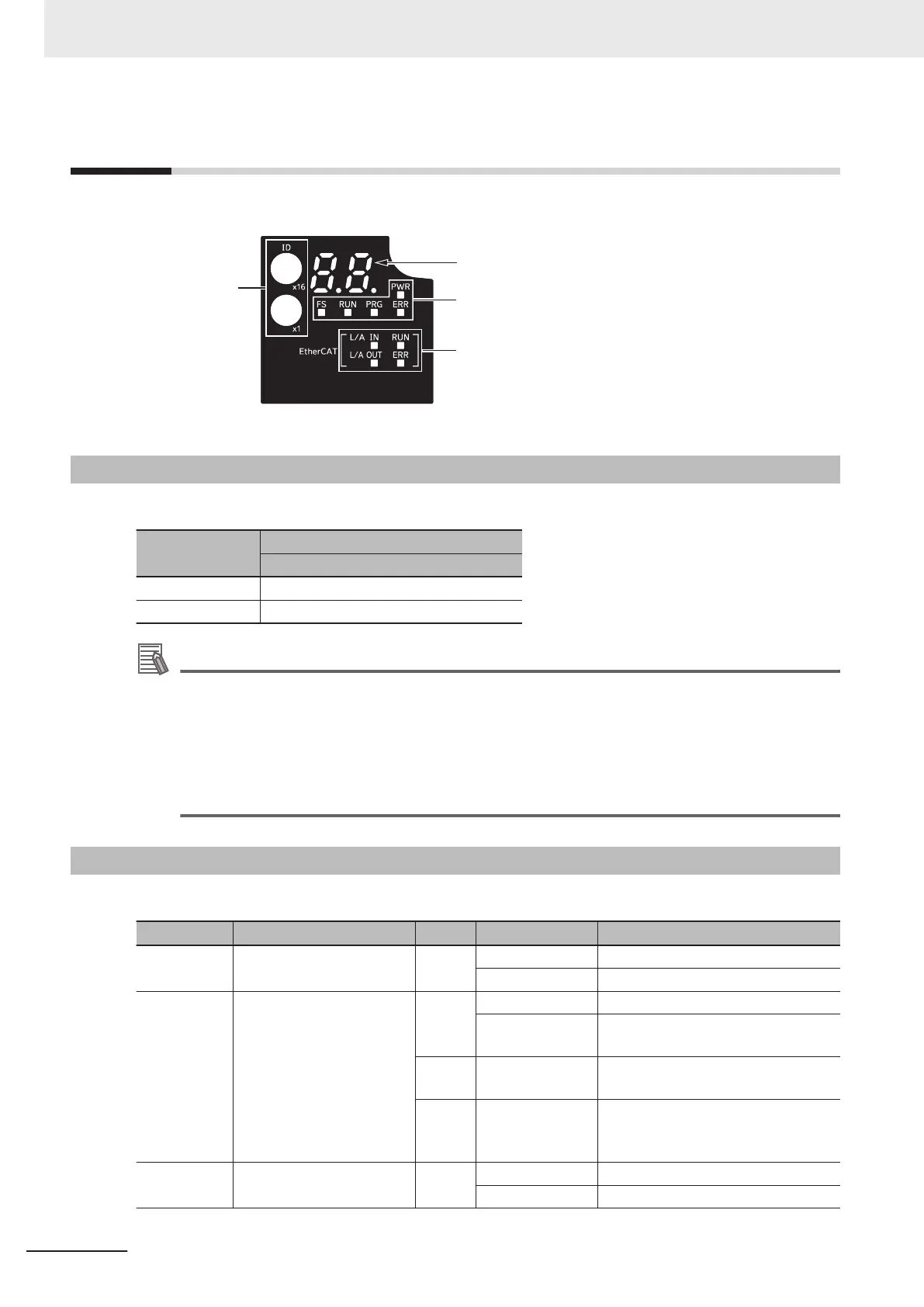
This section explains the indicators and switches located on the front of the inverter.
ID switches
EtherCAT LED
Inverter status LED
Display area
3-1-1
Node Address Setting
Use the ID switches located in the display area to set the EtherCAT node address.
ID switch setting
Description
Connection to NJ/NX-series CPU Unit
00 The controller sets the node address.
01 to FF The ID switches set the node address.
Additional Information
• The ID switch setting is read only once when the Unit power supply is turned ON. Although
the setting is changed after the Unit power supply is ON, it is not reflected in the control. It is
enabled the next time the Unit power supply is turned ON.
• EtherCA
T Slave Information File
Information on EtherCA
T slave settings is stored in the ESI (EtherCAT Slave Information) file.
The master uses the information in this file to configure the network and set communications
parameters. This information is in an XML file.
3-1-2
Name of Each Status Indicator
The following table shows the status indicators and their meaning.
Name Function Color Status Description
Power indi-
cator
Indicates the status of con-
trol power supply.
Green OFF Control power supply OFF
ON Control power supply ON
FS indicator Indicates FSoE communi-
cations status.
Green ON FSoE slave connection established
Flashing FSoE slave connection establish-
ment in progress
Red Flashing Safety Parameter Error, Safety Com-
munications T
imeout, or other errors
---
OFF STO via FSoE is disabled, the power
is not supplied, or a fatal error includ-
ing Self-diagnosis Error
RUN (Opera-
tion) indicator
Indicates that the inverter
is running.
Green OFF Stopped
ON Running
3 EtherCAT Communications
3-2
M1 Series EtherCAT Type User’s Manual (I670)
 Loading...


