4-1-2
Function Object Mapping
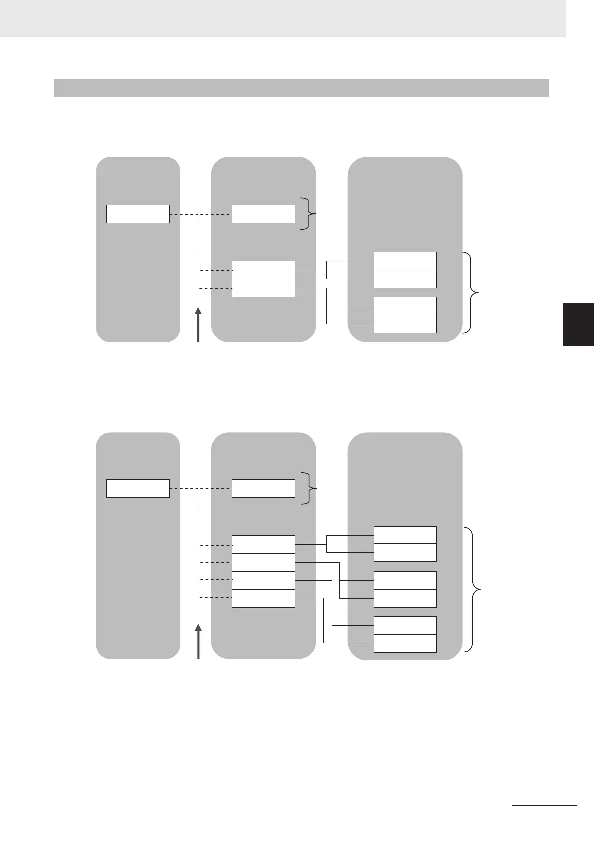
Allocation of function objects is realized through the hierarchical structure shown in the figure below.
Allocation is performed using a tool that is compatible with the Master Unit.
Master to slave
Slave to master
1C13 hex
1C12 hex
Fixed allocation
1701 hex
1700 hex
1600 hex
6040 hex
6042 hex
5000 hex
5010 hex
Fixed allocation
1B00 hex
1B01 hex
6041 hex
5100 hex
5110 hex
10F3 hex
6043 hex
Function object
Function object
Up to 10 function objects
(32 bytes maximum) can
be allocated to 1600 hex.
Nothing is allocated
before shipment.
Sync
Manager
Sync
Manager
PDO Mapping
object
PDO Mapping
object
Up to 10 function objects
(38 bytes maximum) can
be allocated to 1A00 hex.
Nothing is allocated before
shipment.
1A00 hex
1BFE hex
Up to three PDO Mapping objects can be allocated.
Up to three PDO Mapping objects can be allocated.
1BFF hex
2002 hex
4 Inverter Control
4-3
M1 Series EtherCAT Type User’s Manual (I670)
4-1 Outline
4
4-1-2 Function Object Mapping
 Loading...


