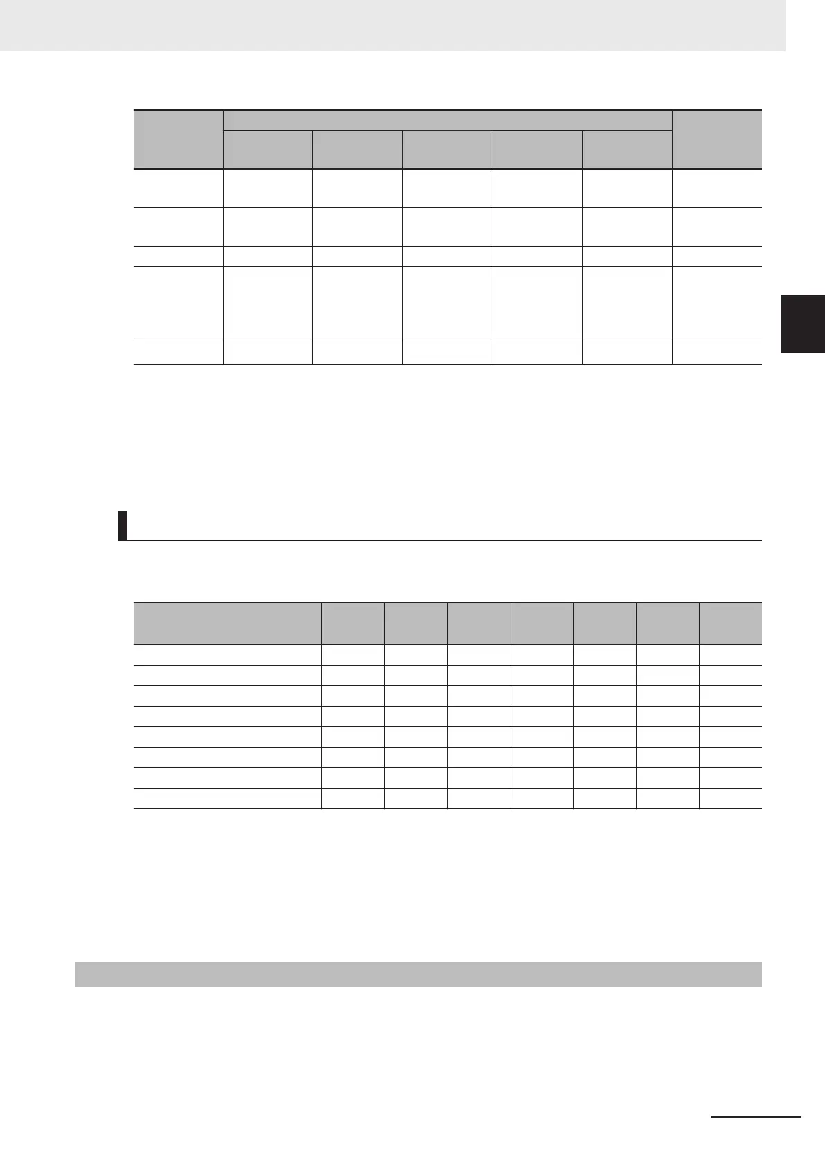
Command
Controlword bit
Move to
Bit 7
fr
Bit 3
eo
Bit 2
qs
Bit 1
ev
Bit 0
so
Disable oper-
ation
Disabled
0 1 1 1 5
Enable opera-
tion
Disabled
1 1 1 1 4
Quick stop
Disabled
1 0 1 1 11
Disable volt-
age
(During quick
stop active)
Disabled
0
Disabled
0 0 12
Fault reset
0 → 1
*2
Disabled Disabled Disabled Disabled
15
*1. The state automatically changes to Operation enabled state after Switched on state.
*2. Bit 7: Operation when the Fault Reset bit turns ON
Fault state : Errors are reset and the inverter returns to the Switch on disabled state.
State other than Fault state : The state will change according to command bits 0 to 3.
After you execute a Fault reset by bit 7, return it to "0" before issuing the next command.
State Coding
State is indicated by the combination of bits in Statusword (6041 hex), as shown in the following ta-
ble.
Status
Bit 6
sod
*1
Bit 5
qs
*2
Bit 4
ve
*3
Bit 3
f
*4
Bit 2
oe
*5
Bit 1
so
*6
Bit 0
rtso
*7
Not ready to switch on 0 0 0 0 0 0 0
Switch on disabled 1
Disabled Disabled
0 0 0 0
Ready to switch on 0 1
Disabled
0 0 0 1
Switched on 0 1
Disabled
0 0 1 1
Operation enabled 0 1
Disabled
0 1 1 1
Quick stop active 0 0
Disabled
0 1 1 1
Fault reaction active 0
Disabled Disabled
1 1 1 1
Fault 0
Disabled Disabled
1 0 0 0
*1. sod = switch on disabled
*2. qs = quick stop
*3. ve = voltage enabled
*4. f = fault
*5. oe = operation enabled
*6. so = switched on
*7. rtso = ready to switch on
A-1-2
Modes of Operation
The inverter supports the following operation mode.
vl: Velocity mode
T
o set the operation mode, use Modes of operation (6060 hex). The operation mode is displayed in
Modes of operation display (6061 hex).
Appendices
A-5
M1 Series EtherCAT Type User’s Manual (I670)
A-1 CiA 402 Drive Profile
A
A-1-2 Modes of Operation
 Loading...


