2-2-2
Terminal Blocks
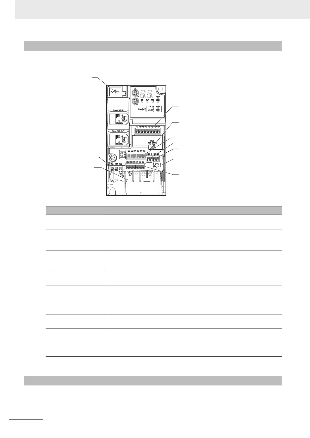
Removing the terminal block cover and each connector cover reveals terminal blocks, connectors, and
switches arranged as shown below
.
USB connector
(Micro-B)
Relay output
terminal block
Main circuit
terminal block
Control circuit terminal block A
Digital input sink/source selector switch (SW1)
Control circuit terminal block B
Safety input terminal block
Auxiliary power supply input terminal
Safety function selector switch (SW
9)
Control circuit terminal block C
Name Description
Digital input sink/source
selector switch (SW1)
The switch for switching which of sink or source the digital input terminals DI1 to
DI7 are to be used for. (Factory default setting is SINK side)
Safety function selector
switch (SW9)
T
urn this switch OFF to use the safety function. Before you turn ON/OFF this
switch, be sure to turn off the power supply
. For details, refer to 8-6 Safety Function
on page 8-61. (Factory default setting is ON side (safety function disabled))
USB connector The Micro-B type USB connector for connecting a computer.
Use this connector to connect the inverter to the Inverter/Servo support tool Sys-
mac Studio.
Control circuit terminal
block A, B, C
The terminal block for connecting various digital/analog input devices used for in-
verter control.
Safety input terminal
block
The terminal block for connecting the safety input signal.
Relay output terminal
block
The SPDT contact terminal block for relay output.
Main circuit terminal block The terminal block for connecting the main power supply for the inverter, outputs to
the motor
, braking resistor
, etc.
Auxiliary power supply in-
put terminal
Backup power supply for control circuit/communication function. The P24 terminal
is insulated from the +24 terminal.
For details on specifications, refer to 2-3-3 Arrangement and Function of Control
Circuit Terminal Block on page
2-12.
Note
For the description of the data display, refer to Section 5 Operation and Test Run on page 5-1.
2-2-3
Preparing Backing Plate
On some models, sometimes there is not enough space for wiring the main circuit. If this happens,
before wiring, cut of
f the connecting points between the backing plate and unnecessary portions with
nippers or a wire cutter
.
2 Design
2-8
M1 Series EtherCAT Type User’s Manual (I670)
 Loading...


