Bit Symbol Description
3 - Control Method
0000: V/f control without slip compensation
0001: Dynamic torque vector control
0010: V/f control with slip compensation
0011: V/f control with speed sensor
0100: Dynamic torque vector control with speed sensor
0101: V
ector control without speed sensor
0110: Vector control with speed sensor
1011: Torque control (vector control with speed sensor)
2 -
1 -
0 -
8-1-2
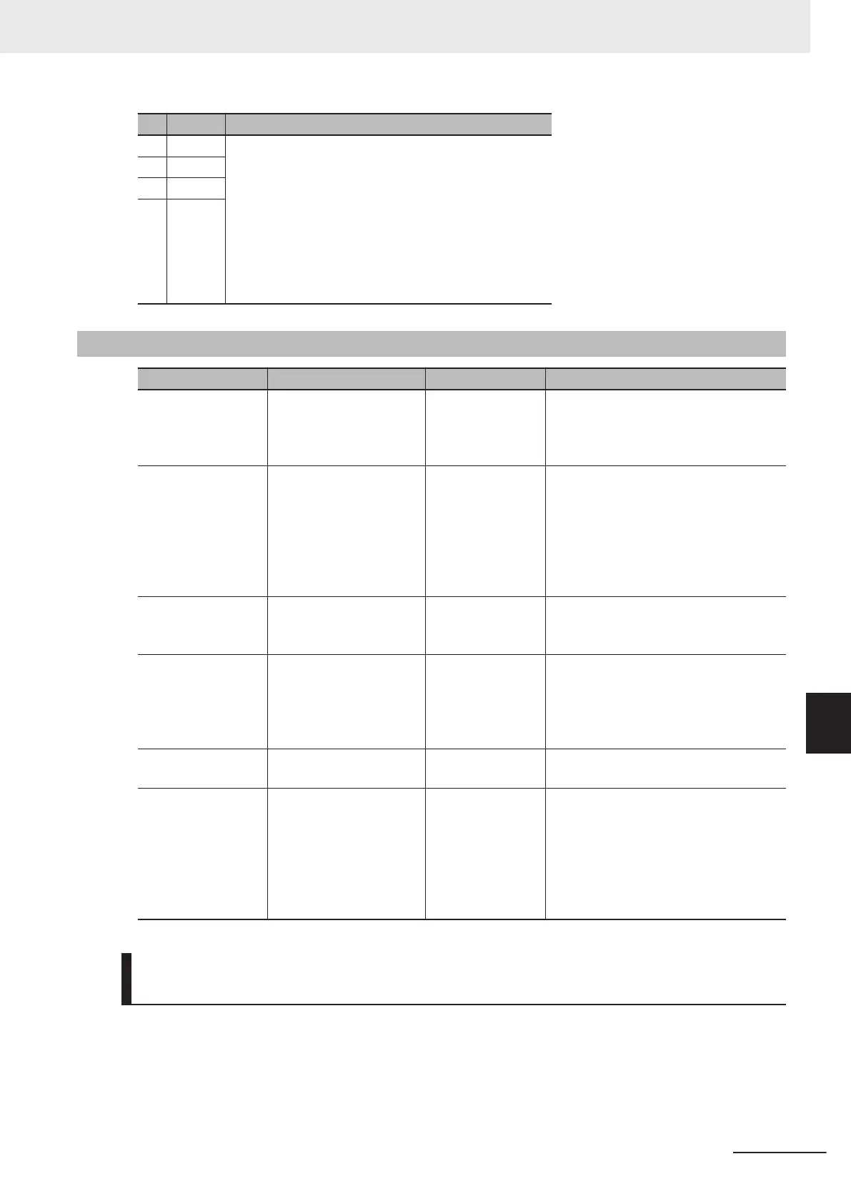
I/O check
Parameter No. Item Range Display item
3010Hex-29Hex,
3010Hex-2AHex
Input Terminal Monitor,
Output Signal Monitor
0000 hex to FFFF
hex
Displays the ON/OFF status of the input
terminals [DI1] to [DI7], output terminals
[DO1], [ROA, ROB] and the [EN1] and
[EN2] terminals.
3010Hex-2BHex,
3010Hex-2CHex
Communications Input
Signal Monitor, Commu-
nications Control Output
Signal Monitor
0000Hex to
FFFFHex
Displays the ON/OFF status of the input
terminals [DI1] to [DI7], [EN1], [EN2],
RST (reset command), REV (reverse
command), FWD (forward command)
and the output terminals [DO1], [ROA,
ROB] instructed via communication
based on RS-485.
3010Hex-2DHex
Input Terminal [AI1] Input
Voltage Monitor
0.0 to 12.0 [V]
The input voltage of the analog input
terminal [AI1] is displayed in increments
of 0.1 V.
3010Hex-38Hex
Pulse Input (A/B Phase
[PIA][PIB])
-327.68 to 327.67
[p/s]
The pulse rate entered in the pulse in-
put terminal [PIA] [PIB] is displayed. (in
increments of 0.01 [kp/s])
Displayed without quad edge evaluation
regardless of the pulse format.
3010Hex-39Hex
Pulse Input (Z Phase
[PIB])
0 to 16000 [p/s]
The pulse rate entered in the pulse in-
put terminal [PIZ] is displayed.
301
1Hex-62Hex
Input Input Terminal
[PTC] Input V
oltage
-12.0 to 12.0 [V]
The thermistor input terminal [PTC] in-
put voltage is displayed in increments of
0.1 V.
*Since this item is shared with other ter-
minal functions, “999” is displayed when
it is disabled due to switching by the
hardware SW
.
Digital Input/Output Terminal Monitor [3010Hex-29Hex,
3010Hex-2AHex]
The status of I/O allocated to each bit for the digital input/output terminal monitor is indicated by a four-
digit hexadecimal.
The allocation for 0 to 15 bits of the terminal I/O status is described in the table below.
Input T
erminal Monitor [3010Hex-29Hex]
8 Other Functions
8-9
M1 Series EtherCAT Type User’s Manual (I670)
8-1 Status Monitors
8
8-1-2 I/O check
 Loading...


