9-2
Troubleshooting
If you feel that the inverter operation is strange or that the inverter does not operate as intended, use
the following information as a reference, even if the inverter displays no alarm indication.
If the inverter trips with an alarm indication, refer to 9-1 Alarm Display and Remedies on page 9-2.
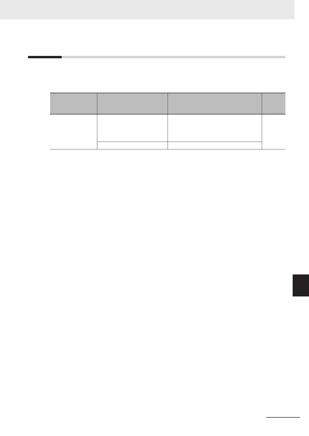
Symptom Possible cause Remedy
Refer-
ence
page
The power supply is
not turned on. (The
POWER LED on the
inverter is not lit.)
The short-circuit bar between
the terminal +1 and P/+2 is re-
moved, or no DC reactor is con-
nected.
Install the short-circuit bar, or connect a DC
reactor
.
page
2-10
page
2-53
Input wiring is disconnected.
Check the input wiring.
9 Troubleshooting
9-29
M1 Series EtherCAT Type User’s Manual (I670)
9-2 Troubleshooting
9

 Loading...


