6 Programming
6-130
NJ-series CPU Unit Software User’s Manual (W501)
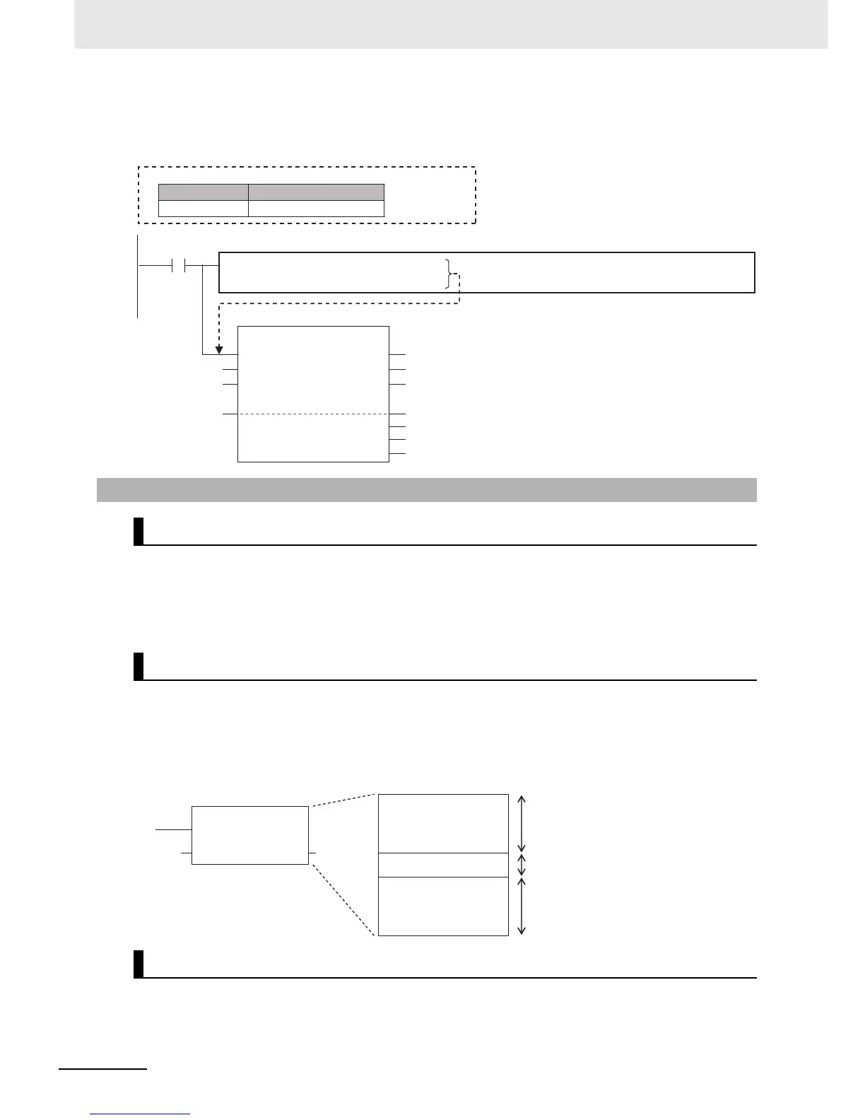
In this case, you must create a structure variable for the input, output, and in-out parameters, then use
the MOVE instruction to set the values.
Example:
Master control is used to make output FALSE for all processing between the MC (Master Control Start)
instruction and the MCR (Master Control End) instruction. Master control is useful to control the execu-
tion conditions of a relatively long series of instructions.
Refer to information on the MC and MCR instructions in the NJ-series Instructions Reference Manual
(Cat. No. W502) for details.
You can use master control in ladder diagrams.
You cannot use master control with ST. You also cannot use master control for inline ST inside a ladder
diagram.
Example:
Inside a Master Control Region:
Refer to information on the MC and MCR instructions in the NJ-series Instructions Reference Manual
(Cat. No. W502) for the operation of other instructions in the master control region when master control
is reset.
6-9-3 Master Control
Introduction
Master Control Programming Languages
Operation of Instructions That Are Reset in a Master Control Region
Execution
condition
Inline ST: Sets values in the Inport structure variable.
Variable Table
Variable name Data type
InPort _sPORT
1
InPort.UnitNo
:=_CBU_No00;
2
InPort.PhysicPortNo
:=USINT#2;
// Serial Communications Unit with unit number 0
// Serial port 2
SerialRcv
Execute
Port
Size
DstDat
ErrorIDEx
RcvSize
SerialRcv_instance
InPort
UINT#13
RecvDat[0] RecvDat[0]
RecvSize
Done
Busy
Error
ErrorID
Programs
User-defined
function block
Ladder diagram algorithm
Inline ST
Ladder diagram algorithm
Nothing is done.
The ladder diagram is reset by the master
control.
For example, the output variables from OUT
instructions change to FALSE.
The ladder diagram is reset by the master
control.
For example, the output variables from OUT
instructions change to FALSE.