Short instructions for configuring a reversing starter
SIMOCODE pro
2-4 GWA 4NEB 631 6050-22 DS 03
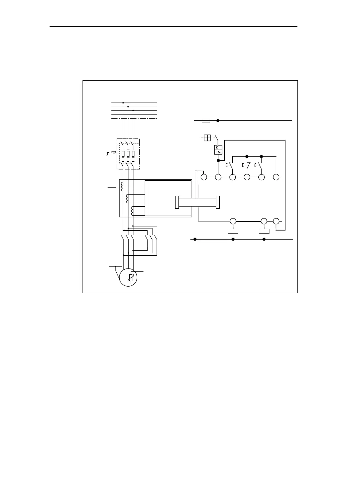
Reversing starter circuitry with SIMOCODE pro
The following schematic shows the circuitry of the main circuit and the
control circuit:
Fig. 2-1: Wiring of the main circuit and the control circuit with SIMOCODE pro
Main circuit
Control circuit
3/N/PE ~ 50/60 Hz 400/230 V
L1
L2
L3
N
PE
Q1
- Q1
135
246
135
M
3~
J
PE
WVU
246
Current measuring
module (IM)
L1/L+
F11
Q1
N/L–
S0
S1
A2 A1
Motor, motor rated current e.g. 3 A
Basic unit (BU)
3 through-hole
openings
System
interface
Connecting cable
System
interface
S2
Q2
CLASS 10
Optional: Thermistor
135
246
- Q2
IN1 IN2
IN3 24 V
OUT1 OUT2 1

 Loading...


