Short instructions for configuring a reversing starter
SIMOCODE pro
GWA 4NEB 631 6050-22 DS 03
2-5
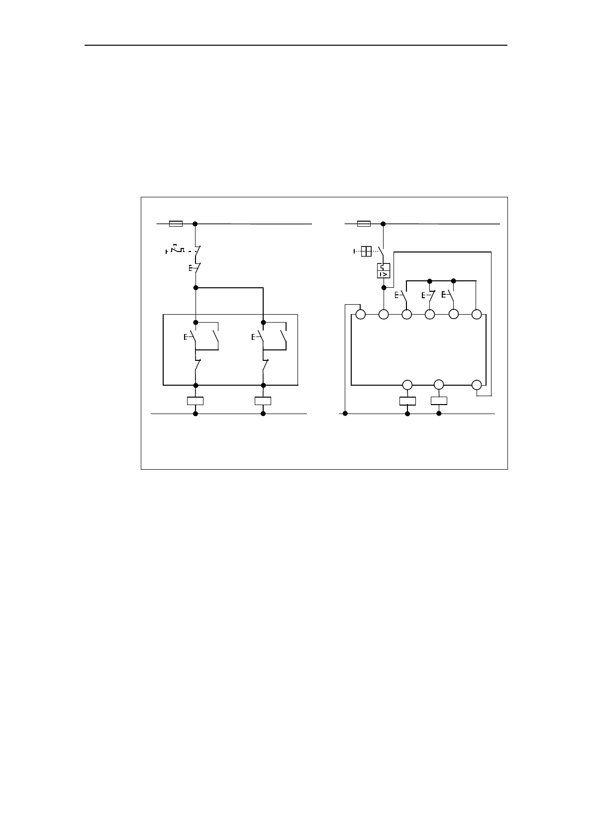
Circuit diagram of a reversing starter control circuit
The following schematic shows the circuit diagram of the control circuit with
a local control station for the commands:
•LEFT
•OFF
•RIGHT.
Displays, messages, etc. have not been taken into account.
Fig. 2-2: Circuit diagram of a reversing starter control circuit
The necessary interlocks and connections are carried out in the basic unit
via software.
Standard reversing starter Reversing starter with SIMOCODE pro
Necessary interlocks
and connections
S0: "LEFT" button
S1: "OFF" button
S2: "RIGHT" button
Q1: Contactor clockwise rotation
Q2: Contactor counterclockwise rotation
L1/L+
F11
Q1
N/L–
S0
S1
A2
A1
Basic unit (BU)
Q2
S2
L1/L+
N/L–
Q2
Q2
Q1
S2
S1
Q1
Q2
S0
Q1
IN1 IN2 IN3 24 V
OUT1 OUT2 1

 Loading...


