4-4. Rear Panel
4-4-1. Removal and Installation of Rear Panel Assembly
Preparation
1. Remove the cover. (Refer to “4-2-1. Power Block Assembly (D00)”)
2. Remove the plug-in board on the rear side. (Refer to “4-5-2. Installing/Removing Plug-in Boards and Blank Panels
on the Rear Side”)
Procedure
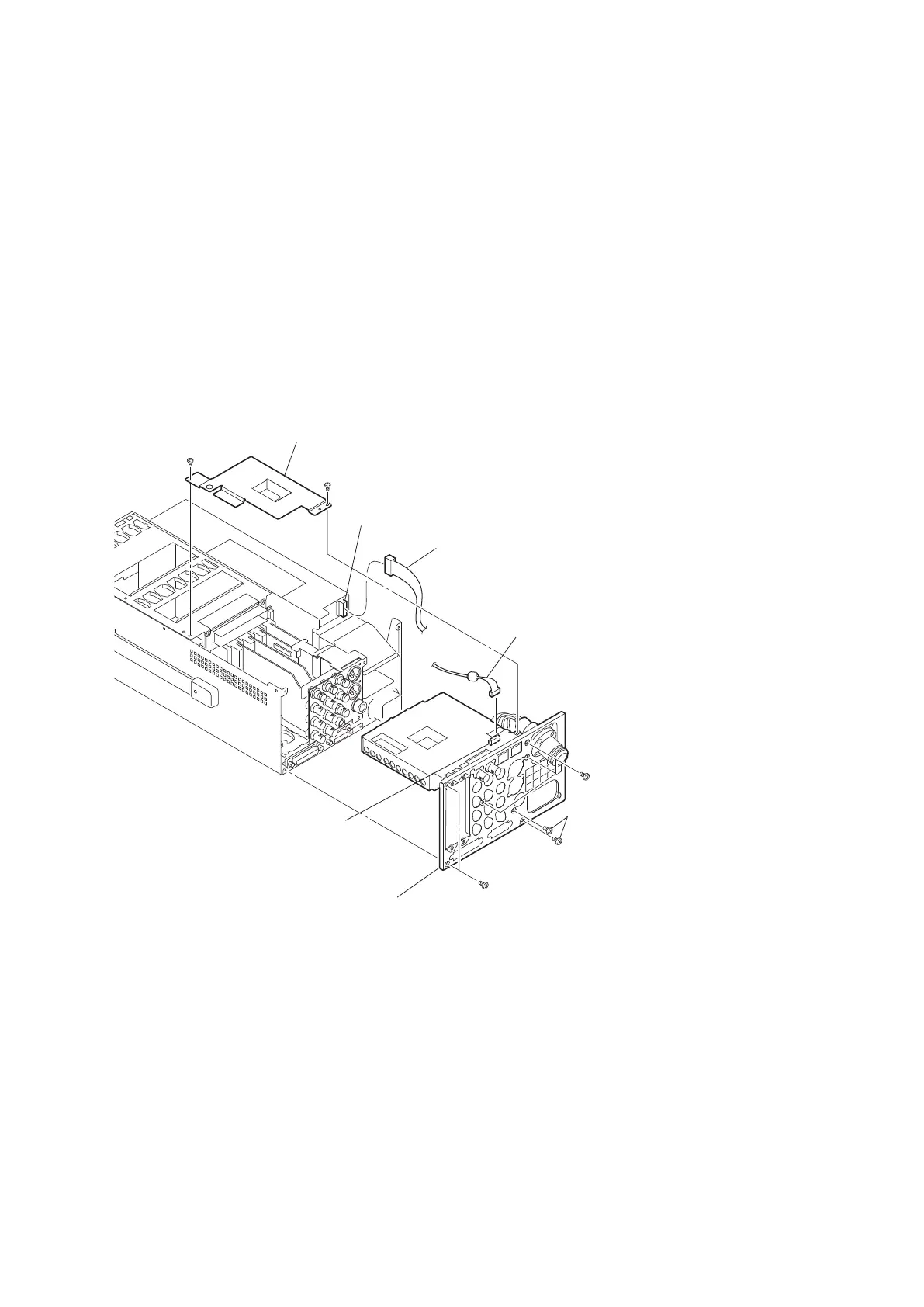
1. Disconnect the harness from the connector CN900 on the SDP-17 board.
2. Disconnect the harness from the connector on the power block assembly.
3. Remove the two screws, and remove the heat spreader (P) .
4. Remove the eight screws, and remove the rear panel assembly.
B3 x 5
B3 x 5
B3 x 5
B3 x 5
B3 x 5
Rear panel assembly
CN900
(SDP-17 board)
Connector
(Power block assembly)
Heat spreader (P)
Harness
Harness
5. Install the removed parts by reversing the steps of removal.
4-4-2. SDP-17 Board
Preparation
1. Remove the rear panel assembly. (Refer to “4-4-1. Removal and Installation of Rear Panel Assembly”)
Procedure
1. Remove the four screws, and remove the cover (SDP-17) and the fiber cable cover.
2. Disconnect the harness from the connector CN200 on the SDP-17 board.
HDCU2500
4-16

 Loading...


