3-3. SYSTEM OPERATION Menu
S01: OUTPUT SELECT
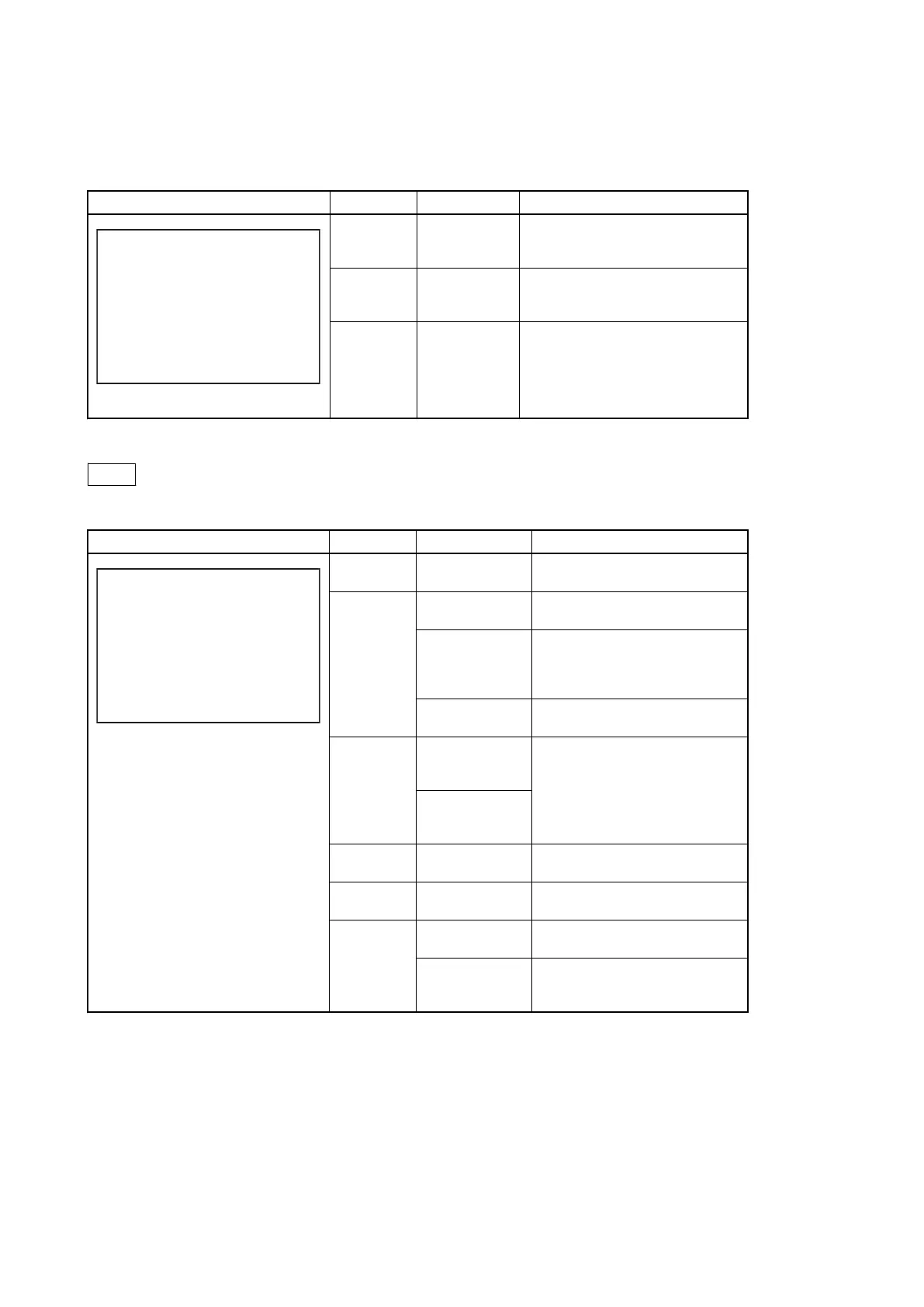
Menu Image Item Settings Description
<OUTPUT SELECT> S01 TOP
OUTPUT:*CAMERA
BAR
TEST1
TEST2
PIX:*ENC R G B
R&G G&B R&B RGB
WFM:*ENC R G B SEQ
R&G G&B R&B RGB
OUTPUT CAMERA,
BAR, TEST1,
TEST2
Selects the output signal.
TEST1 and TEST2 are not selectable if
there is no communication with the camera
PIX ENC, R, G, B,
R&G, G&B,
R&B, RGB
Selects the PIX connector output signal.
WFM ENC, R, G, B,
SEQ, R&G,
G&B, R&B,
RGB
Selects the WFM connector output signal.
S02: GENLOCK PHASE
Note
SUB-REF displayed only when HKCU1003 is installed
Menu Image Item Settings Description
<GENLOCK PHASE> S02 TOP
REFERENCE (NONE)
GENLOCK : SD (OK)
H STEP : 0.00usec
COARSE: 0
V PHASE : 0
SUB-REF :(NONE)
(UNKNOWN)
REFER-
ENCE
(NONE), (EXT IN) Displays whether reference signal input
is present. (Display only)
GENLOCK
HD, SD This unit’s GEN LOCK mode: displays
the lock status and format.
(OK) , (NG) Sets the lock status of the external refer-
ence signal.
(OK): Lock
(NG): Unlock
External reference
signal format
Displayed only when a reference signal
is present.
H STEP When GENLOCK
mode is HD: -3.01
to 3.45 µsec
Adjusts the reference signal lock phase.
Horizontal phase (STEP)
When GENLOCK
mode is SD: -8.29 to
9.48 µsec
COARSE -99.9 to 99.9 Adjusts the reference signal lock phase.
Horizontal phase
V PHASE 0 to 7 Adjusts the reference signal lock phase.
Vertical phase (in units of line)
SUB-REF (NONE), (EXT IN) Displays whether sub-reference signal
input is present. (Display only)
(UNKNOWN),
(Frame Gate), (HD),
(SD)
Sub-reference signal format display
(Display only)
HDCU2500
3-10

 Loading...


