5-3. Video/Reference Signal System Adjustment
5-3-1. 27 MHz VCO Free-Running Adjustment
Measuring equipment
• Frequency counter
• Oscilloscope
Preparation
• Extend the AT-167A board using an extended board.
• Disconnect the cable from the REFERENCE INPUT connector.
• REFERENCE switch on the panel of AT-167A board → SD
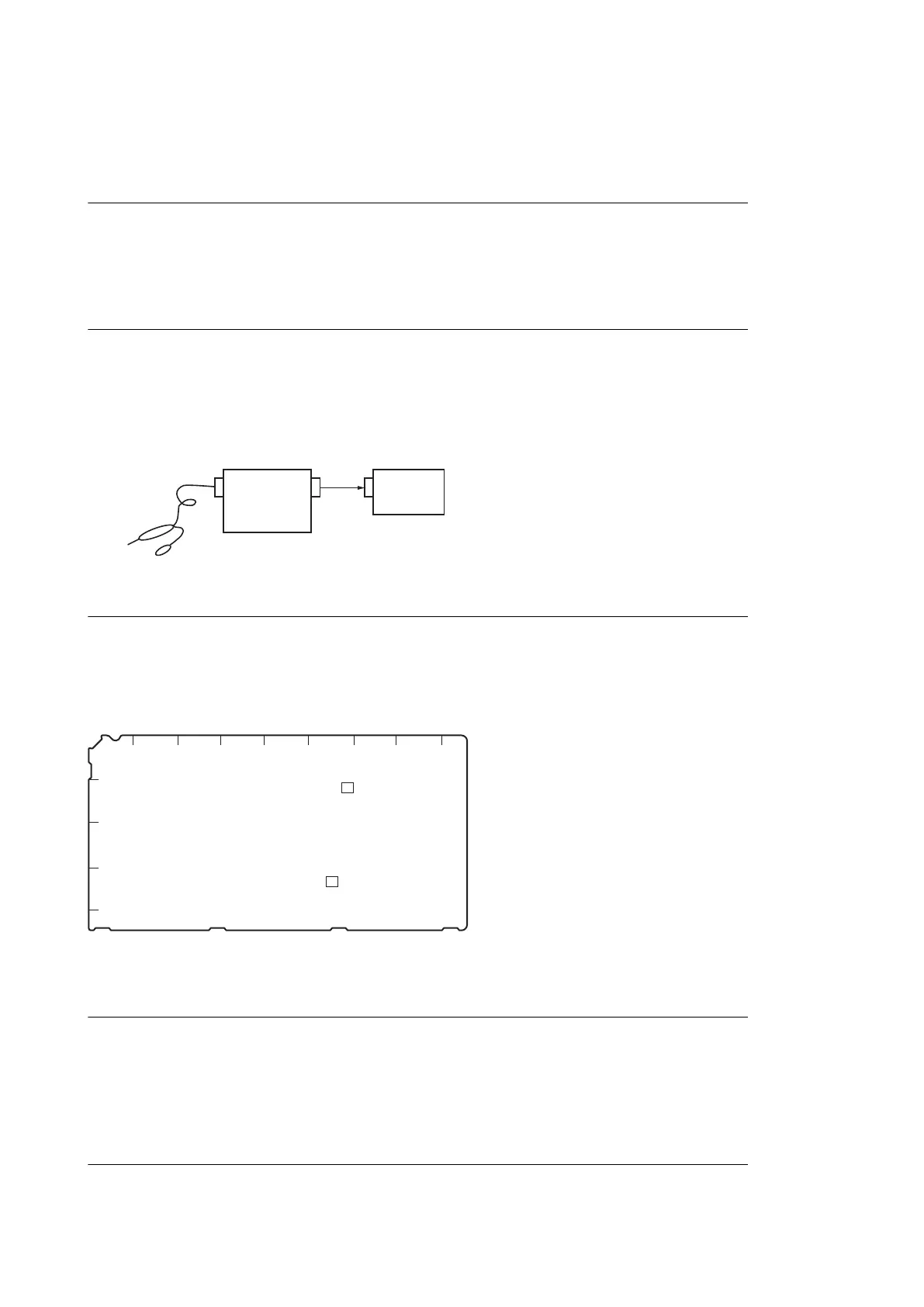
• Connect the measuring equipment as shown in the following figure.
CH2
IN
CH2
OUT
IN
Probe
Oscilloscope
Frequency counter
Adjustment Procedure
Test Point: TP704 (F-4)/ AT-167A board
Adjusting Point: RV701 (F-2)/ AT-167A board
Specification: 27,000,000 ±10 Hz
AT-167A board (Side A )
A B C D E F G H J
1
2
3
4
5
RV701
TP704
Setting after Adjustment
After this adjustment is completed, set the switch to the previous state and reconnect the disconnected cable.
5-3-2. Clock (74 MHz) Duty Adjustment
Measuring equipment
Oscilloscope (20 MHz BWLimit: ON)
HDCU2500
5-7

 Loading...


