Adjustment Procedure
1. Press the BARS button of the MSU-1000/1500 or RCP-1500/1501 to display the color bars on the waveform
monitor.
2. Adjust the color bar signal with potentiometer RV303 (VBS LEVEL) on the EN-159A/159B board so that it is
within the specified level.
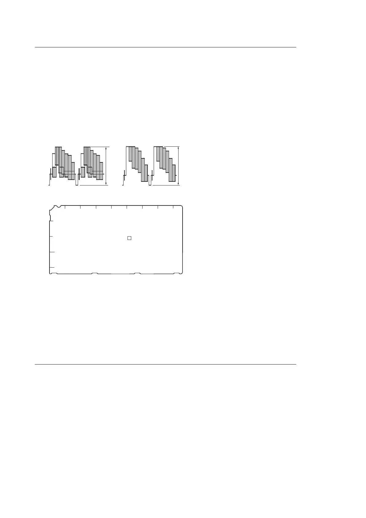
Test Point: VBS OUT connector/rear panel
Specification:
A = 140 ±1 IRE (75 Ω termination)
B = 1000 ±7 mVp-p (75 Ω termination)
BA
NTSC
PAL
1
2
3
4
5
RV303
EN-159A/159B (Side A)
A B C D E F G H J
2-5-5. Waveform Monitor Signal Level Adjustment (Only When HKCU1001/1003
is Installed)
The video output signal of the unit can be checked using the waveform monitor connected to the WF OUT connector.
Adjust the WF output signal level using the color bar signal.
Adjustment Procedure Using EN-159A/159B Board
1. Press the BARS button of the MSU-1000/1500 or RCP-1500/1501.
2. Press the ENC button of the WAVEFORM MONITOR button of M SU-1000/1500 or MONITOR SELECT button
of RCP-1500/1501 to display color bars on the waveform monitor.
HDCU2500
2-17

 Loading...


