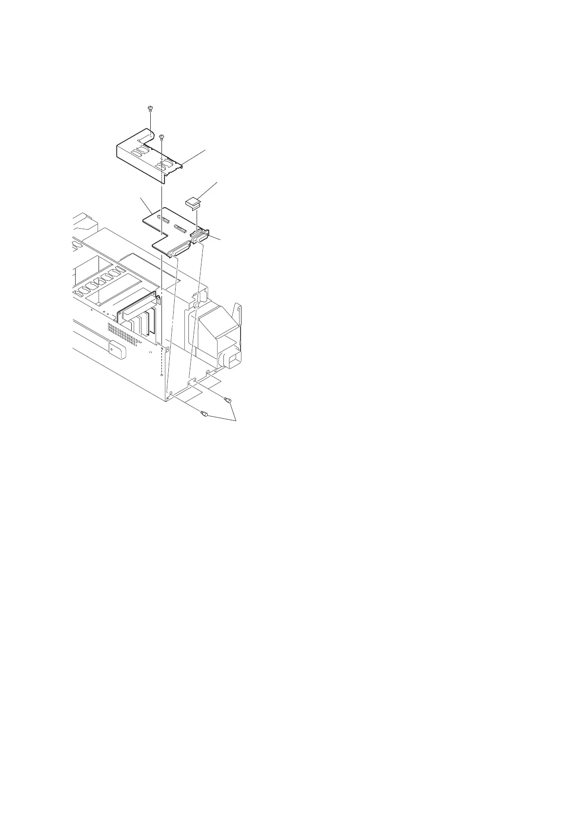
3. Remove the four screws (supplied with connector) , and remove the CNB-29A board.
B3 x 5
B3 x 5
Screws
(supplied with connector)
CN3
CNB-29A board
Flexible flat cable
PWB guide (rear)
4. Install the removed parts by reversing the steps of removal.
4-6-9. MB-1181 Board
Preparation
1. Remove the rear panel assembly. (Refer to “4-4-1. Removal and Installation of Rear Panel Assembly”)
2. Remove the all plug-in boards. (Refer to “4-5. Plug-In Board”)
3. Remove the rear sub assembly (included in the HIF-62 board and the SDI-99 board). (Refer to “4-6-1. HIF-62
Board”)
4. Remove the ADO-12 board. (Refer to “4-6-7. ADO-12 Board”)
5. Remove the VIF-52 board. (Refer to “4-6-6. VIF-52 Board” )
6. Remove the PWB guide (rear). (Refer to “4-6-8. CNB-29A Board”)
Procedure
1. Disconnect the harness from the connector CN31 on the MB-1181 board.
2. Remove the four screws, and disconnect the flexible flat cable from the connector CN32 on the MB-1181 board.
HDCU2500
4-28

 Loading...


