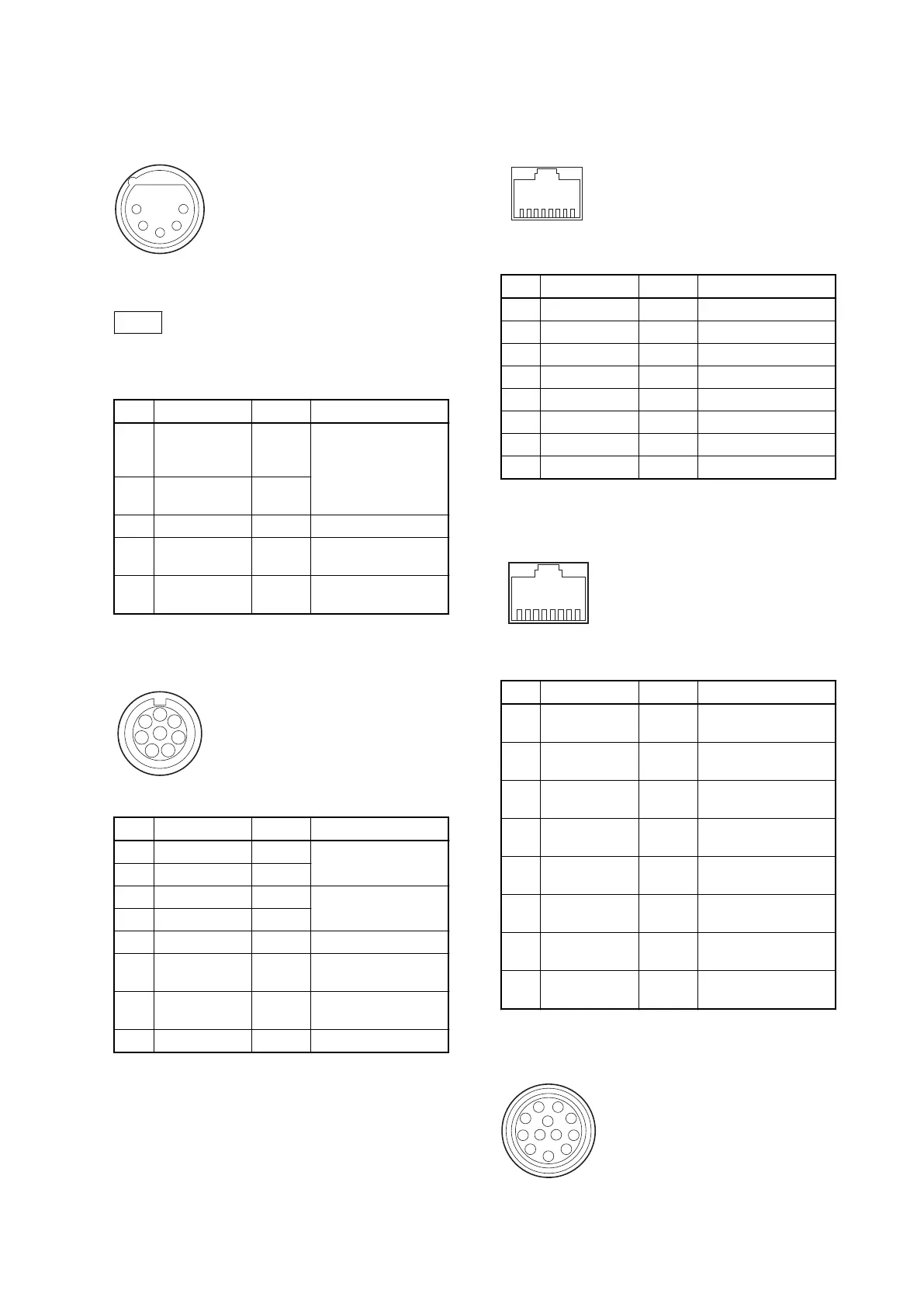
11. INTERCOM
- External View -
1
2
5
4
3
XLR 5-pin, Female
(0 dBu = 0.775 V rms)
Note
In the UNBALANCE mode, connect the GND signal of the
microphone to Pin 1
No. Signal I/O Specifications
1 INTERCOM
MIC IN (Y)/
(GND)
I –20 dBu (CARBON )
–40 dBu (ECM)
–60 dBu (DYNAMIC,
BALANCE/UNBAL-
ANCE)
2 INTERCOM
MIC IN (X)
I
3 GND — GND
4 INTERCOM L
OUT
O —
5 INTERCOM R
OUT
O —
12. RCP/CNU
1
7
6
5
4
3
2
8
- External View -
8-pin, Female
No. Signal I/O Specifications
1 TX (+) O SERIAL DATA OUT
2 TX (–) O
3 RX (+) I SERIAL DATA IN
4 RX (–) I
5 TX GND — GND for TX
6 POWER (+)
OUT
O RCP POWER, +30 V
7 POWER (–)
OUT
O GND for POWER
8 VIDEO (X) O 75 Ω, 1.0 V p-p
13. LAN
18
- External View -
8-pin, RJ-45, 10Base-T/100Base-TX
No. Signal I/O Specifications
1 TXD (+) O Transmitted Data (+)
2 TXD (–) O Transmitted Data (–)
3 RXD (+) I Received Data (+)
4 NC — No connection
5 NC — No connection
6 RXD (–) I Received Data (–)
7 NC — No connection
8 NC — No connection
14. NETWORK TRUNK
8-pin, RJ-45, 10Base-T/100Base-TX/1000Base-TX
- External View -
81
No. Signal I/O Specifications
1 TRD 0 (+) I/O Transmitted/Received
Data 0 (+)
2 TRD 0 (–) I/O Transmitted/Received
Data 0 (–)
3 TRD 1 (+) I/O Transmitted/Received
Data 1 (+)
4 TRD 2 (+) I/O Transmitted/Received
Data 2 (+)
5 TRD 2 (–) I/O Transmitted/Received
Data 2 (–)
6 TRD 1 (–) I/O Transmitted/Received
Data 1 (–)
7 TRD 3 (+) I/O Transmitted/Received
Data 3 (+)
8 TRD 3 (–) I/O Transmitted/Received
Data 3 (–)
15. TRUNK A
12-pin, Female
- External View -
A
B
C
D
J
K
LM
H
G
F
E
HDCU2500
1-4

 Loading...


