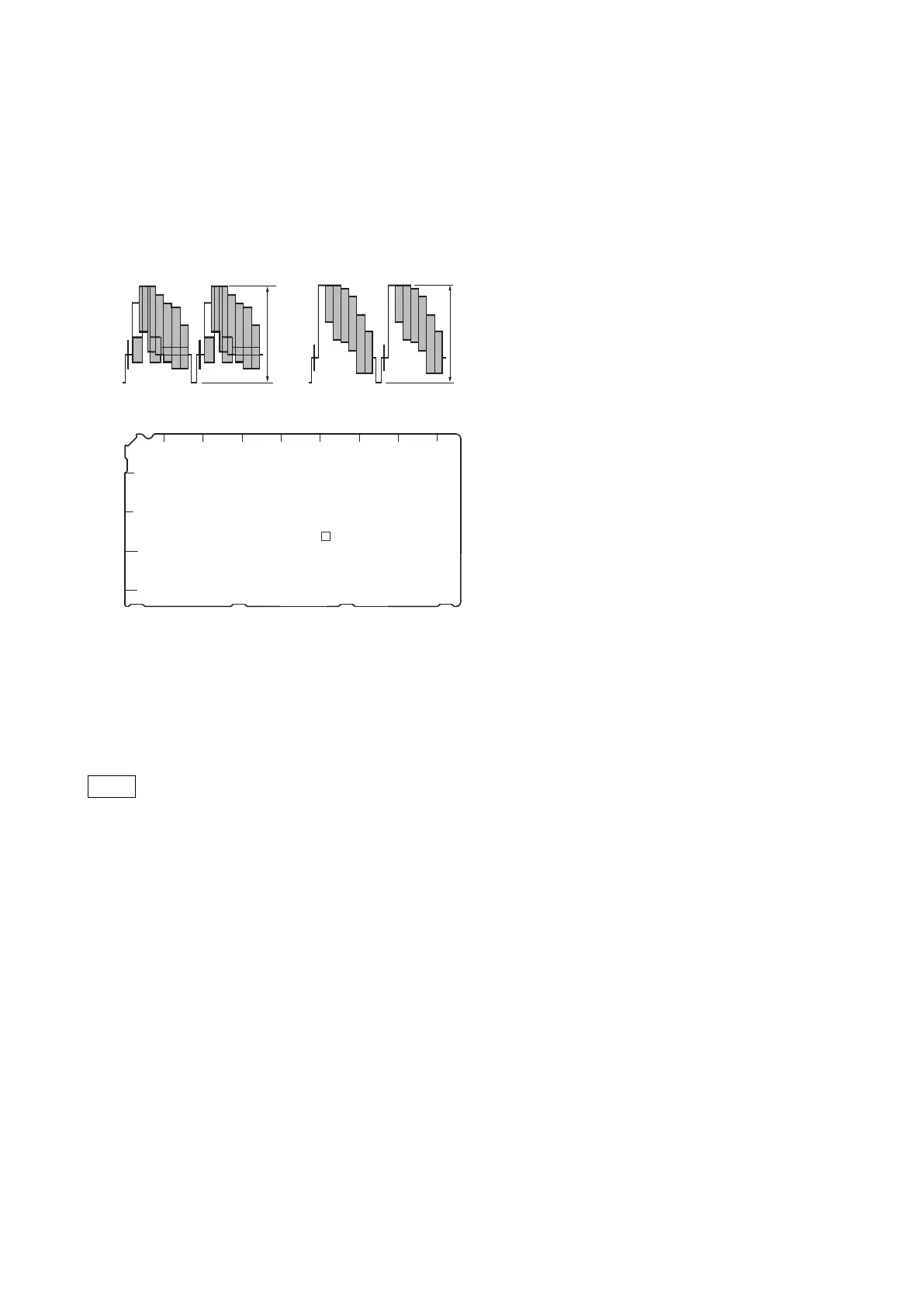
3. Adjust the color bar signal with potentiometer RV304 (PIX GAIN) on the EN-159A/159B board so that it is within
the specified level.
Test Point: PIX OUT connector/rear panel
Specification:
A = 140 ±1 IRE (75 Ω termination)
B = 1000 ±7 mVp-p (75 Ω termination)
BA
NTSC
PAL
1
2
3
4
5
EN-159A/159B (Side A)
A B C D E F G H J
RV304
2-5-8. RETURN Input Signal
Set the format of the return signal to be input to the RET1, RET2, and RET3 connector using the maintenance menu of
MSU-1000/1500 or S07: RETURN SETUP in the SYSTEM OPERATION menu of this unit.
Note
When required, either of the PROMPTER connectors can be assigned for the fourth return video input (RET4),
exclusively for analog VBS signals.
HDCU2500
2-20

 Loading...


