5-2. Audio System Adjustment
5-2-1. RTS Intercom Adjustment
Measuring equipment
• Oscilloscope
• Audio oscillator
Precautions
• This adjustment is described on the premise that the output impedance of the audio oscillator is 600 Ω.
• When the intercom system is the RTS system, perform this adjustment.
Preparation
• Extend the AVP-15 board using an extended board.
• CCU CONFIGURATION menu → INTERCOM (C07)
→ ENGINEER: RTS
→ TERMINATION: ON
• CCU CONFIGURATION menu → INTERCOM (C07)
→ PRODUCER: RTS
→ TERMINATION: ON
• CCU CONFIGURATION menu → FRONT INCOM (C08) → INCOM MIC: CARBON
Adjustment Procedure
PROD CANCEL
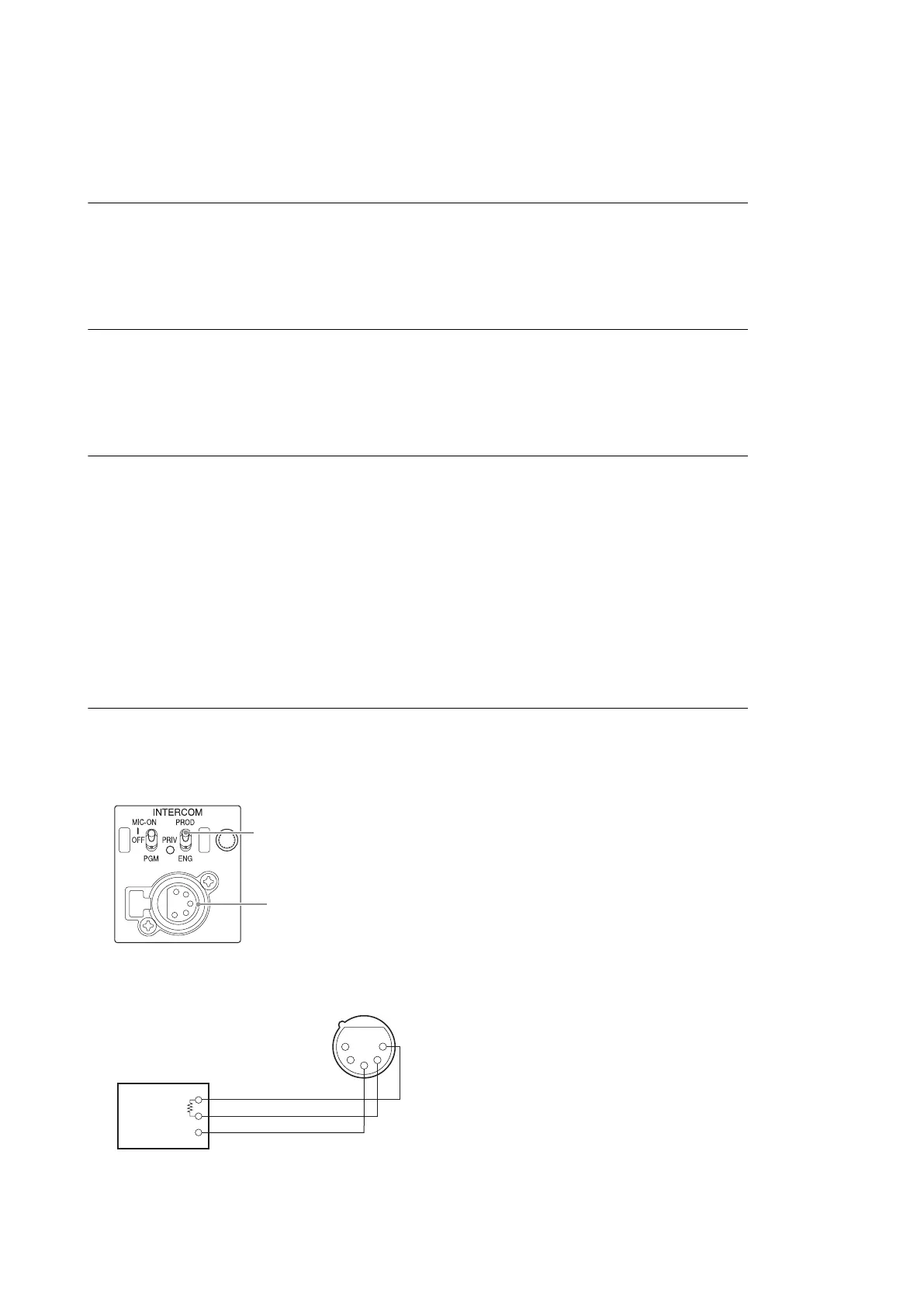
1. Turn the INTERCOM switch on the front panel to PROD side .
INTERCOM switch
INTERCOM connector
2. Input a sine wave (1 kHz, 220 mV p-p (–20 dBu)) to pin 2 (X), pin 1 (Y), and pin 3 (G) of the INTERCOM connector
from the audio oscillator.
HDCU2500
5-4

 Loading...


