Chapter 4 Installing Hardware
4-27
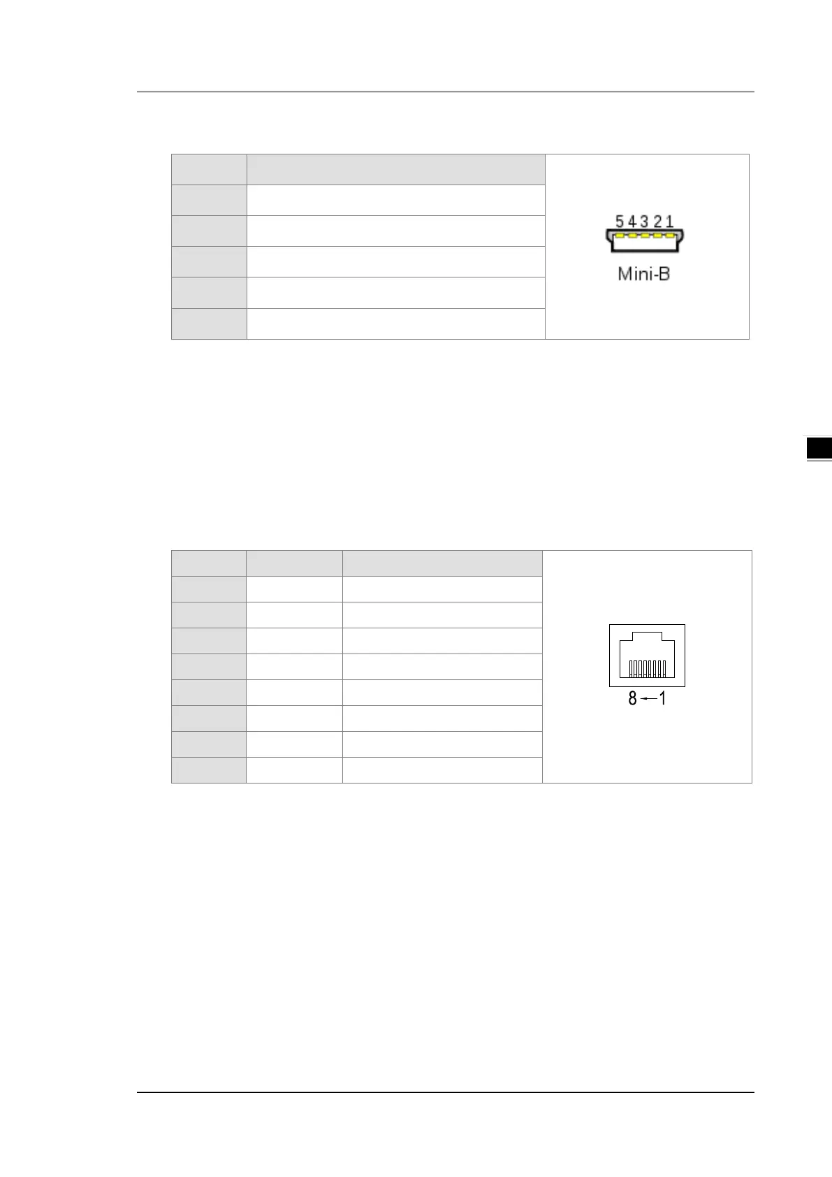
4.1.12 Recommended USB Wiring for the PLC CPU
Pin Function
1 VBUS (4.4–5.25 V)
2 D−
3 D+
4 Ground
5 Ground
When it is the first time to use USB communication, follow the steps below.
Refer to Appendix A : Installing a USB Driver, if it is the first time to use USB port to communicate.
Time to use the USB port: uploading/downloading PLC programs, monitoring during calibration
and upgrading firmware.
NOT suggested to use the USB port: applications that require a long and un-interruptible
communication.
What to do when a communication failure occurs: unplug any communication connector from the
USB port and then plug the connector back. After that reconnect and try communication again.
4.1.13 Recommend Ethernet/EtherCAT Wiring for the PLC
CPU
Pin Signal Description
1 TX+ Transmitting data (positive pole)
2 TX- Transmitting data (negative pole)
3 RX+ Receiving data (positive pole)
4 -- N/C
5 -- N/C
6 RX- Receiving data (negative pole)
7 -- N/C
8 -- N/C
Refer to Chapter 9 and 11 for more details on Ethernet/EtherCAT Wiring.

 Loading...


