Chapter 5 CPU and Module Devices
5-5
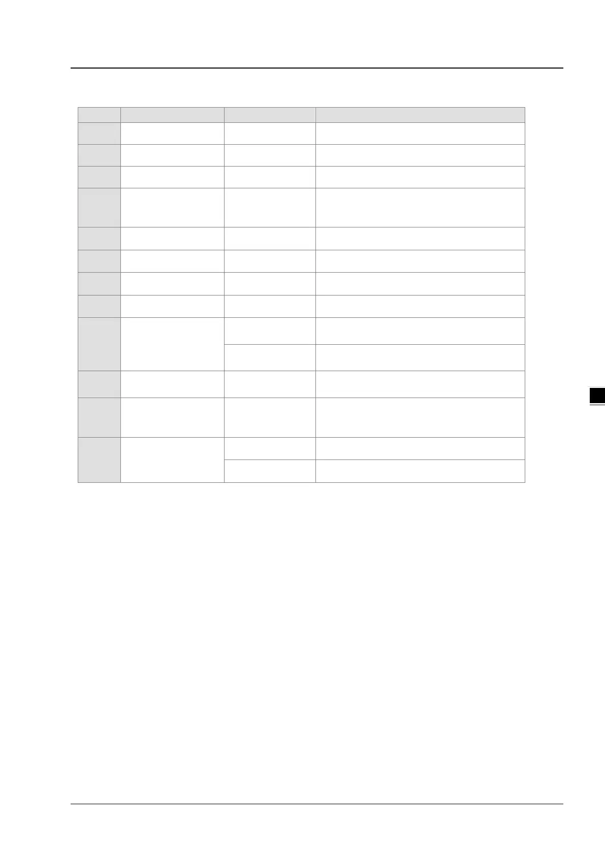
5.1.4 Latched Areas in the Device Range
X Input relay X0–X377
All devices are non-latched.
Y Output relay Y0–Y377
All devices are non-latched.
M*
1
Auxiliary relay M0–M8191 The default range is M6000–M8191.
SM Special auxiliary relay SM0–SM2047
Some devices are latched, and
changed. Refer
to the list of special auxiliary
relays for more information.
S*
1
Flag S0–S2047 The default range is S512–S1023
T Timer T0–T511 All devices are non-latched.
C*
1
Counter C0–C511 The default range is C448–C511
HC*
1
32-bit counter HC0–HC255 The default range is HC128–HC255
D*
1
Data register
D0–D29999 The default range is D20000–D23999
W0–W29999 *
2
FR File register FR0–FR65535 All devices are latched.
SR Special data register SR0–SR2047
Some are latched, and cannot be changed.
Refer to the list of special data registers for more
E Index register
E0–E9 All devices are non-latched.
E10–E14 *
2
*1: For more information on setting the latched area, see HWCONFIG in ISPSoft or Hardware Configuration in
DIADesigner.. Setting the latched area means the other areas are seen as non-latched areas. The range of latched
areas cannot exceed the device range. For example, setting M600–M7000 as latched areas makes M0–M5999 and
M7001–M8191 non-latched areas.
*2: Used for editing in ISPSoft/DIADesigner only.

 Loading...


