DVP-ES3/EX3/SV3/SX3 Series Hardware and Operation Manual
4-54
*1. Use shielded cables to isolate the analog input signal cable from other power cables.
*2. If the module is connected to a current signal, the terminals Vn and In+ (n=0–3) must be short-circuited.
*3. If variability in the input voltage results in interference within the wiring, connect the module to a capacitor
having a capacitance between 0.1–0.47 μF and a working voltage of 25 V.
*4. Use shielded cables to isolate the analog output signal cable from other power cables.
*5. If variability in the input loading results in interference within the wiring, connect the module to a capacitor
having a capacitance between 0.1–0.47 μF and a working voltage of 25 V.
*6. Connect the shielded cable to the terminal FE and to the ground terminal.
*7. Connect the
to the terminal FE.
*8. The wording “CHX-I” indicates that you can use those five wiring methods for every input channel. The
wording “CHX-O” indicates that you can use those two wiring methods for every output channel.
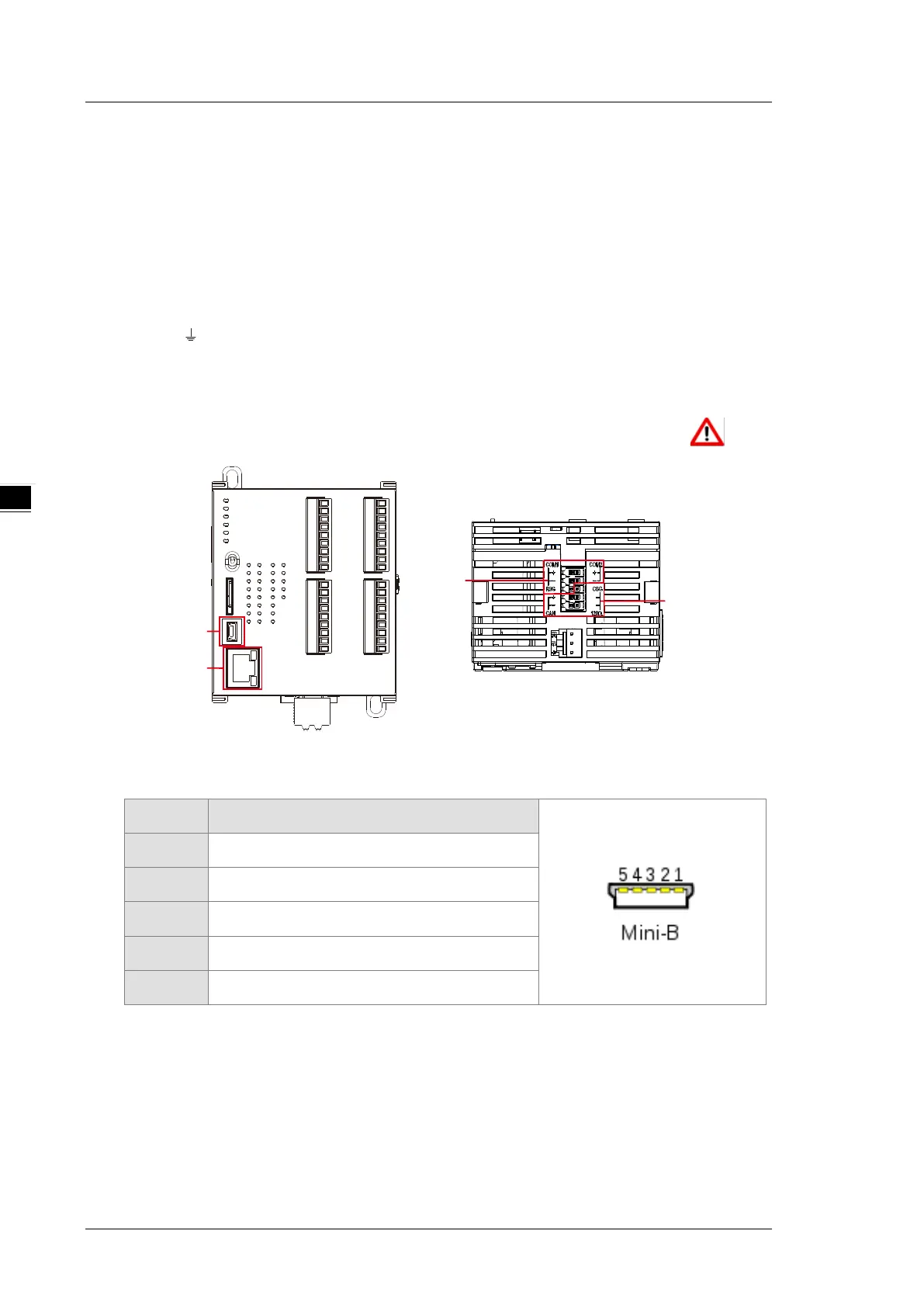
4.2.11 Wiring DVP-SV3/SX3 Communication Ports
USB port
Pin Function
1 VBUS (4.4–5.25 V)
2 D−
3 D+
4 Ground
5 Ground
Refer to Appendix A : Installing a USB Driver, if it is the first time to use USB port to communicate.
Time to use the USB port: uploading/downloading PLC programs, monitoring during calibration
and upgrading firmware.
NOT suggested to use the USB port: applications that require a long and un-interruptible
communication.
What to do when a communication failure occurs: unplug any communication connector from the
USB port and then plug the connector back. After that reconnect and try communication again.

 Loading...


