Chapter 5 CPU and Module Devices
5-15
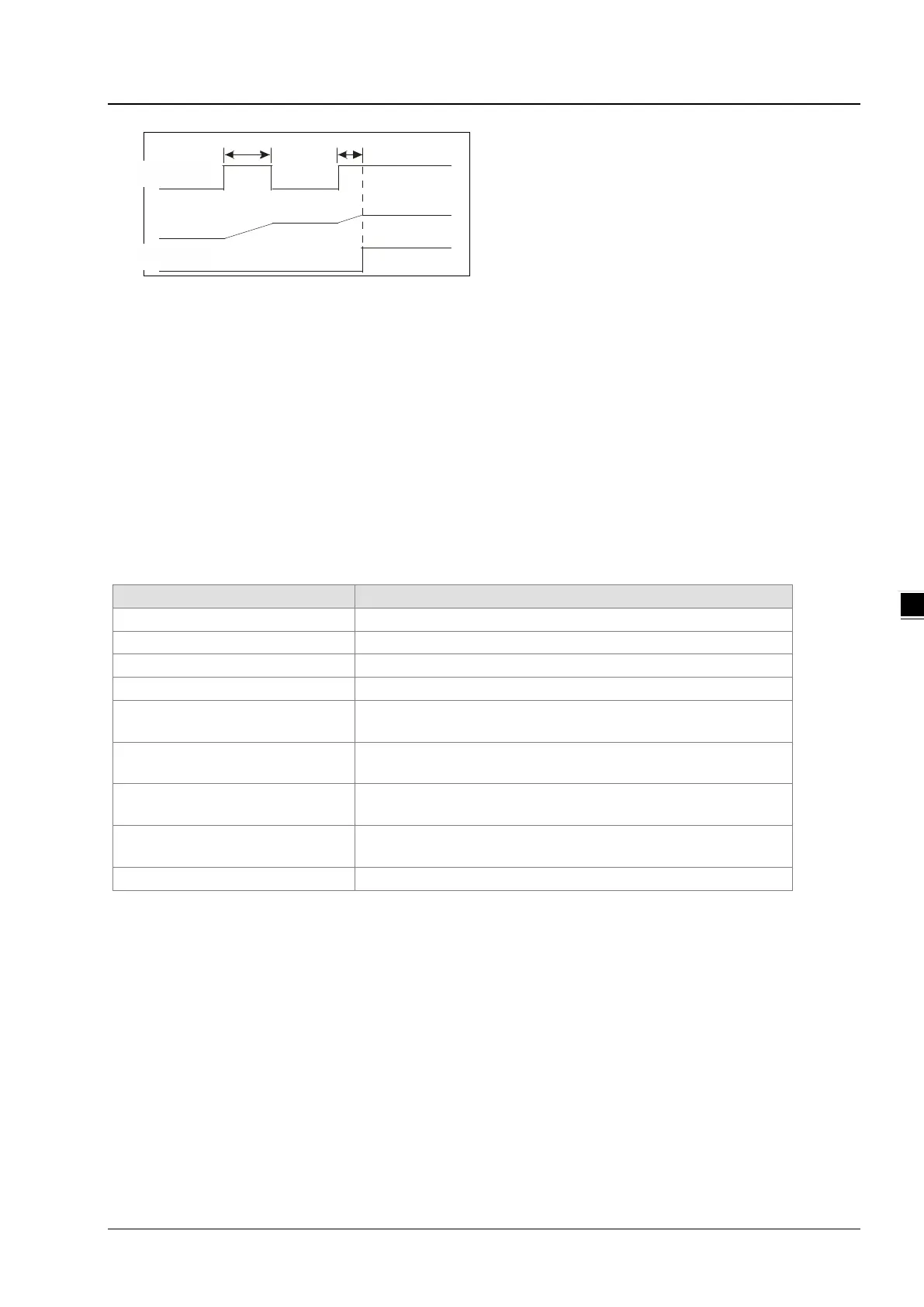
X0.0
T2
Y0. 0
S V: K100
T1+T2=10 sec
T250( P V)
T1
C. Timers used in function blocks
T412–T511 are the timers that you can use in the function block or in interrupts.
When the TMR or END instruction is executed, the timer in the functional block begins to count. When the value of
the timer matches the timer setting value, the output coil is ON.
If you use a general-purpose timer in a function block or an interrupt, and the function or interrupt is not executed, the
timer cannot count correctly.
5.2.10 Counters
Characteristics of the 16-bit counter
Direction Counting up
Specifying the counter setting value
The setting value can be either the constant or the value in the data
Change of the current value
The counter stops counting when the value of the counter matches
the counter setting value.
Output contact
The contact is ON when the value of the counter matches the counter
setting value.
Reset
When the instruction RST is executed, the current value is cleared to
zero, and the contact is reset of OFF.
After the scan is complete, the contact acts.
Function of the counter
Each time the input switches from OFF to ON, the value of the counter is the same as the output coil. You can use
either the decimal constant or the value in the data register as the counter setting value.
16-bit counter:
1. Setting range: 0–32,767. The setting values 0 and 1 mean the same thing in that the output contact is ON when the
counter counts for the first time.
2. For the general-purpose counter, the current value of the counter is cleared when power is lost. If the counter is
latching, the current value of the counter and the state of the contact before power was lost power are retained. The
latched counter counts from the current value when the power supply is restored.

 Loading...


