Chapter 9 Ethernet Specification and Operation
9-31
9.4.5.2 Steps to Set up and Download Parameters
1. Create a data mapping table (*):
Right-click the COM port on the Ethernet Scanner, and click Data Mapping to open the Data Mapping Table.
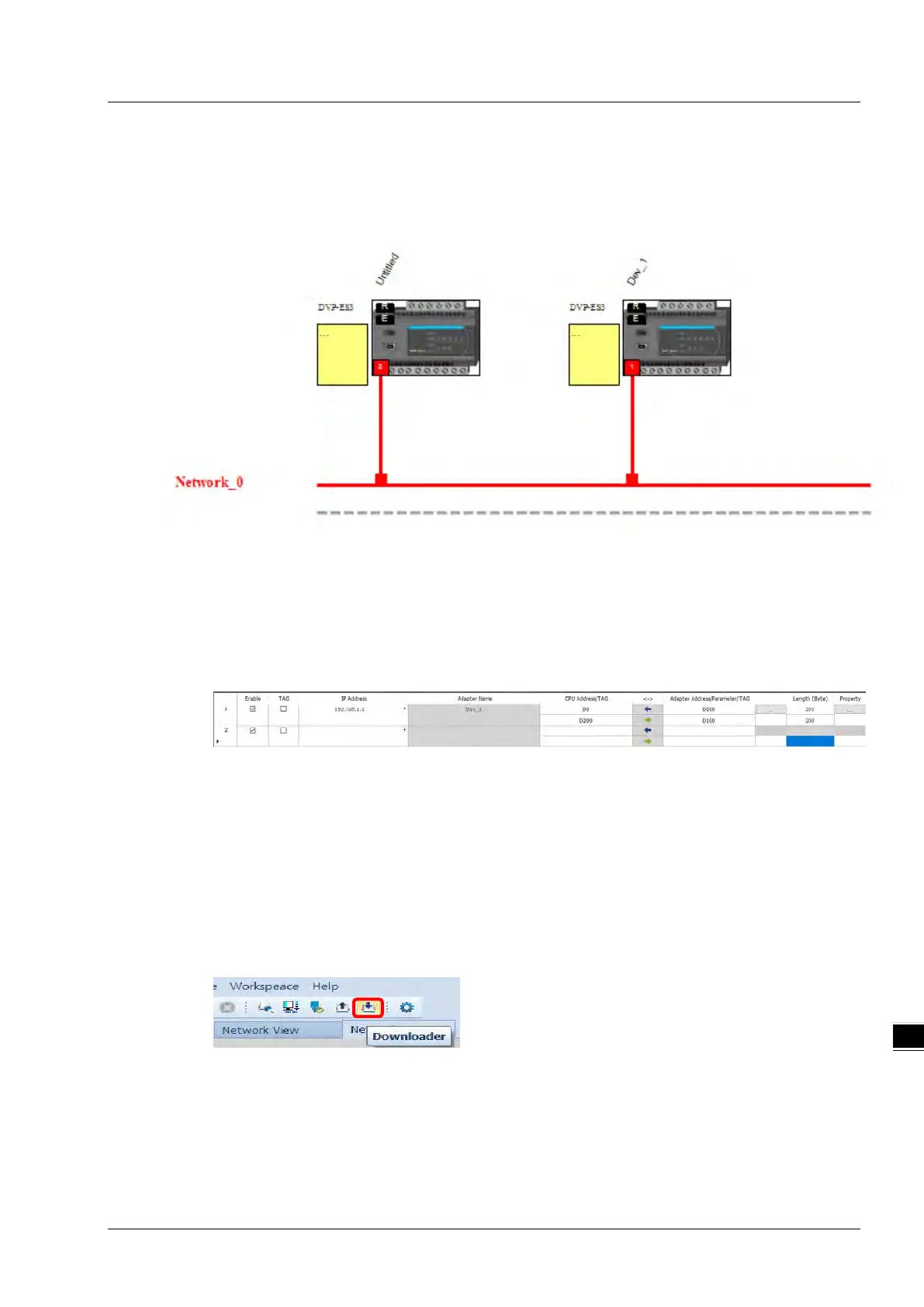
2. Set the Data Mapping Parameters
Type the parameters in the data mapping table. The unit for data length is byte. See the example below.
a) Reading D500–D599 from the Adapter with the IP address 192.168.1.1 to the D0–D99 in the Scanner.
b) Writing D200–D299 from the Scanner to D100–D199 in the Adapter with the IP address 192.168.1.1
c) One Adapter can create multiple connections for data mapping. Each IP address corresponds to one
independent TCP connection and each row represents one independent CIP connection. The number of
connections cannot exceed the maximum number of connections for the Scanner. For the ES3 PLC
CPU, the maximum number of connections is 8.
d) Properties: Set the advanced data mapping parameters.
e) Click Download.
* There is no need to use registers when using TAG function to perform data mapping. You can enter the IP
address to establish a connection to the tag of other device. Refer to the next section for more details on
TAG.

 Loading...


