Chapter 4 Installing Hardware
4-53
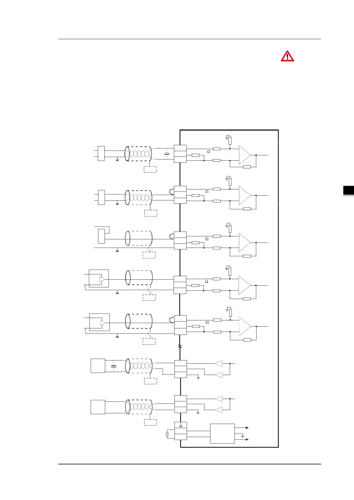
4.2.10 Wiring SX3 Series Analog Input /Output
Terminal definitions
• Two-/three-wire (passive sensor): the sensor and the system share the same power circuit.
• Four-wire (active sensor): the sensor uses an independent power supply and should not share the same
power circuit with the system.
• Use terminals with the same length (less than 200 m) and use terminal resistors of less than 100 ohm.
1M
AG
1M
1M
AG
1M
250
250
VO1
IO1
AG
AG
VO0
IO0
AG
Voltage o utput
-10V~+10V
*5
AG
24VDC
DC/DC
Converter
+15V
-15V
AG
*7
*6
*6
FE
FE
1M
AG
1M
250
Shielded c able*1
4 voltage i nput-:
-10V~+10V
V1+
I1+
VI1-
CHX-I
V0+
I0+
VI0-
*3
*2
+
-
V2+
I2+
VI2-
*2
+
-
+
-
+24V
0V
+24V
0V
*6
FE
+24V
0V
1M
AG
1M
250
1M
AG
1M
250
+24V
+
-
V1+
I1+
VI1-
*2
+24V
+
-
*6
FE
*6
FE
0V
0V
FE
*6
FE
*6
0V
24V
*8
CHX-I
*8
CHX-I
*8
CHX-I
*8
CHX-I
*8
CHX-O
*8
CHX-O
*8
V3+
I3+
VI3-
Shielded c able*1
Shielded c able*1
-20mA~+20mA
4 wi re current i nput- :
4mA~+20mA
4 wi re current i nput- :
Shielded c able*1
Shielded c able*1
-20mA~+20mA
3 wi re current i nput- :
-10V~+10V
3 wire voltage i nput- :
0mA~20mA
Voltage o utput
Shielded c able*4
Shielded c able*4
AC motor drive,
recorder,
proportioning v alue
AC motor drive,
recorder,
proportioning v alue

 Loading...


