DVP-ES3/EX3/SV3/SX3 Series Hardware and Operation Manual
4-44
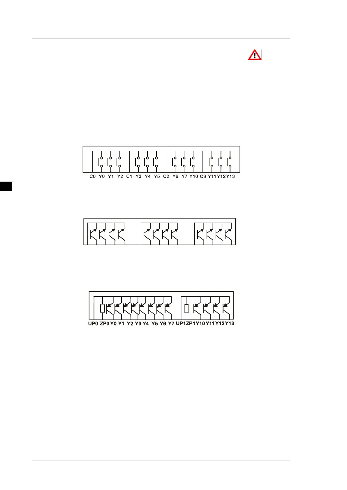
4.2.7 Wiring Digital Output Terminals on DVP-SV3 Series
1. There are two types of output modules: relays and transistors. When wiring the output terminals, pay
attention to the connection of the common terminals.
2. For relay models, the output terminals Y0, Y1, and Y2 share the common terminal C0; Y3, Y4, and Y5
share the common terminal C1; Y6, Y7, and Y10 share the common terminal C2; Y11, Y12, and Y13 share
the common terminal C3. Operation indication: When there is any activity on the output point, its indicator light
on the front will be ON.
3. For transistor models (NPN), the output terminals Y0, Y1, Y2 and Y3 share the common terminal C0; Y4,
Y5, Y6 and Y7 share the common terminal C1; Y10, Y11, Y12 and Y13 share the common terminal C2.
C2 Y10 Y11 Y12 Y13C0 Y0 Y1 Y2 Y3 C1 Y4 Y5 Y6 Y7
4. For transistor models (PNP), the output terminals Y0 to Y7 share the common terminals UP0 and ZP0; Y10
to Y13 share the common terminals UP1 and ZP1.
5. Isolation circuit: Optocouplers are used between the internal circuit of the PLC and the input module to
achieve signal isolation.

 Loading...


