Chapter 10 CANopen Function and Operation
10.5 Troubleshooting
10.5.1 CANopen Network Node State Display
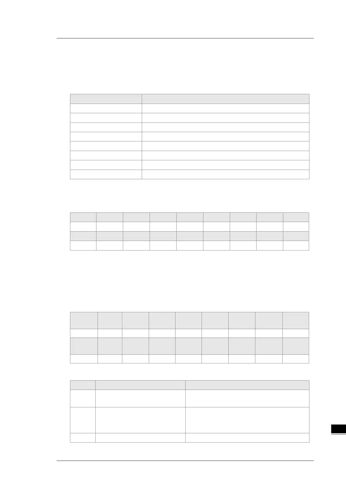
1. In the DVP-ES3/EX3/SV3/SX3 Series PLC, while you enable the CANopen function, it uses SR825–893
as the special registers as shown in the following table.
Displays the state of CANopen DS301 Master
Displays the state of 64 nodes in the network
Flag for the state of the slave 1–16
Flag for the state of the slave 17–32
Flag for the state of the slave 33–48
Flag for the state of the slave 49–64
Displays the CANopen baud rate (unit: 1kpps)
2. As a master, the DVP-ES3/EX3/SV3/SX3 Series PLC supports a maximum of 64 slaves ranging from
node 1 to node 64. You can use SR826–829 to monitor the state of the nodes in the network. The 16 bits
in SR826 correspond to 16 slaves and their corresponding relations are shown in the following table.
When the node in the master node list is normal, the corresponding bit is OFF; when the node in the
master node list is abnormal (for example, initializing fails or the slave is offline for some reason), the
corresponding bit is ON.
3. The error code of every node is displayed through the corresponding special register (SR830–893) and
the relations between special register and corresponding node (1–16) is shown in the following table.
(You can also judge for other correspondings that are not listed here.)
Special
SR830 SR831 SR832 SR833 SR834 SR835 SR836 SR837
Special
SR838 SR839 SR840 SR841 SR842 SR843 SR844 SR845
4. Node codes displayed in SR830–893 when the ASSeries PLC is the master:
0
The node is error free or the node is
N/A
E0
ASSeries PLC master module
receives the emergency message
Read the relevant message with the PLC program
PDO data length returned from the
Set the PDO data length of the slave and

 Loading...


