Chapter 4 Installing Hardware
4-29
Communication cable
Several communication interfaces are included in a CPU module, and many types of network modules
are available. You can choose communication cables to use according to the actual usage situation.
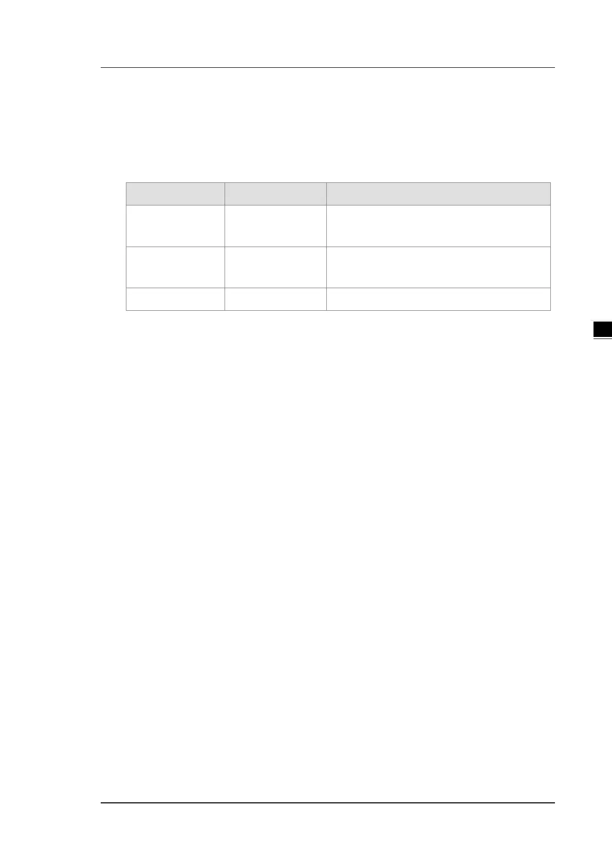
The following table lists information about communication interfaces and main applications.
Interface Connector Application
Communication port
10-pin removable
terminal block
Computer, HMI communication, industrial control
network (2x RS-485)
Ethernet RJ45
Computer, HMI communication, remote control,
data exchange, industrial control network
USB Mini USB Computer communication
Extension modules
Apart from the standard communication ports on a CPU module, the CPU module is equipped with I/O
functions. Refer to section 1.1.3 for a selection of extension modules. You can find a suitable extension
module according to your needs.
The following lists the limits for setting up a common framework of the DVP-SV3/SX3 PLC system. Exceeding
the first three limits causes the PLC to send an error message.
Limit 1: The maximum number of digital I/O points is 512 (256 inputs and 256 outputs). The built-in digital I/O
points of the CPU module are included. (If DI points are 262, and DO points are 60, that means the DI
points exceed the limit range.)
Limit 2: On the right side of the PLC CPU, you can connect up to 8 modules including analog I/O modules,
temperature measurement modules, positioning modules, communication modules.
Limit 3: On the left side of the PLC CPU, you can connect up to 8 modules including high-speed analog I/O
modules, high-speed load cell modules, high-speed communication modules.
Limit 4: The maximum power consumption of CPU module and extension module should be within the range
of what a CPU module or a power module can supply. Refer to section 4.2.5.4 for the maximum power
consumption of modules.
Limit 5: Up to 14 right-side extension modules can be connected to a DVP slim type PLC CPU. The input point
starts from X20 and output point starts from Y20. Refer to the combination example below.

 Loading...


