Chapter 10 CANopen Function and Operation
The following table lists supported transmission modes.
Mode 0: The PDO information is transmitted only when the PDO data changes and the synchronous
signal is received.
Modes 1–240: One piece of PDO information is transmitted every 1–240 synchronous signals.
Mode 254: The trigger is defined the manufacturer. The definition in the PLC is the same as mode
255.
Mode 255: The PDO is transmitted when the data changes, or it is transmitted after a trigger.
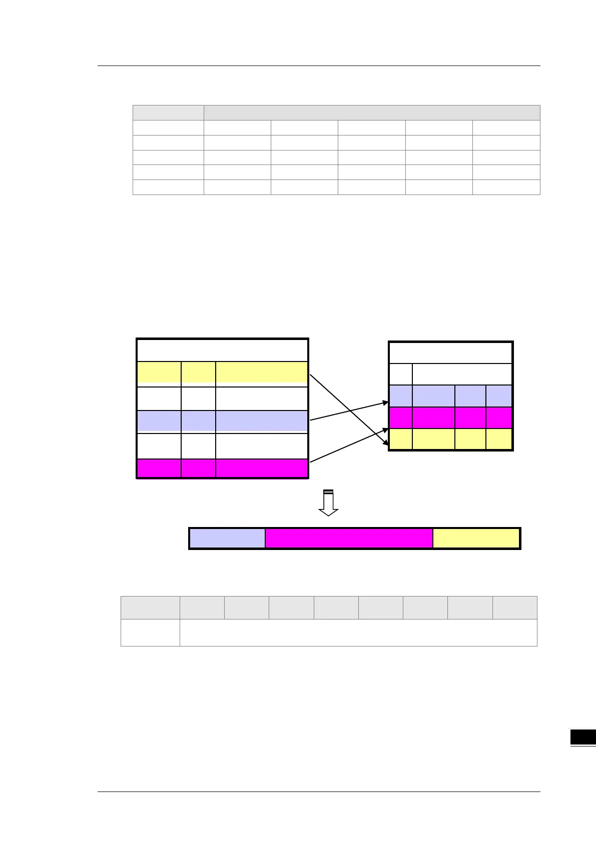
All the data in the PDO has to be mapped from the object dictionary. The following diagram shows an
example of PDO mapping.
The following table shows the data format for RxPDO and TxPDO.
COB-ID Byte 0 Byte 1 Byte 2 Byte 3 Byte 4 Byte 5 Byte 6 Byte 7
Object
identifier
Data

 Loading...


