SC-T7000 series/SC-T5000 series/SC-T3000 series Revision B
DISASSEMBLY & ASSEMBLY Disassembly and Assembly Procedure 101
Confidential
3.4.2.15 LEFT UPPER COVER & LEFT ROLL COVER
1. Remove the UPPER LEFT COVER. (p100)
2. Remove the UPPER SUPPORT R COVER. (p94)
3. Remove the PANEL BOARD. (p120)
4. Remove the TOP COVER. (p85)
5. Remove the FRONT COVER. (p86)
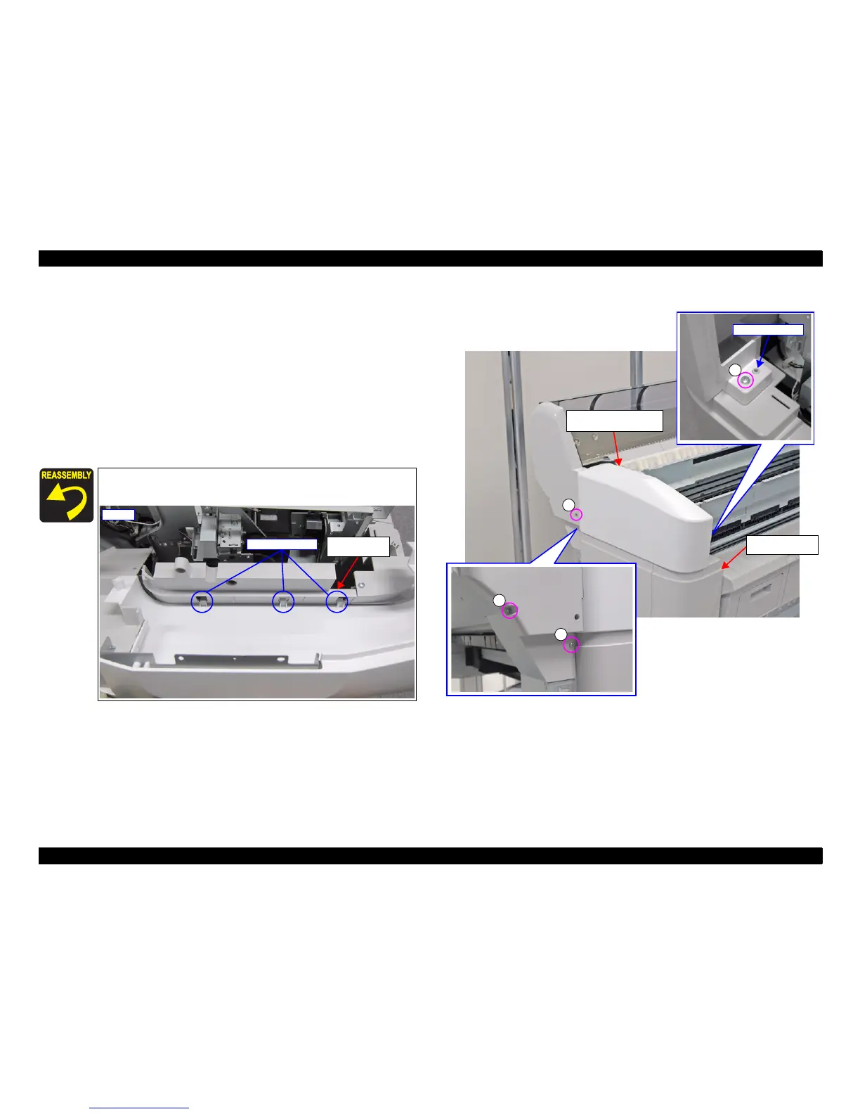
6. Remove the four screws, and remove the LEFT UPPER COVER & LEFT ROLL
COVER.
A) Silver M4x12 P-tite screw with washer: 4 pcs
Figure 3-28. Removing the LEFT UPPER COVER & LEFT ROLL COVER
Pay attention to the positioning points (See below figure, Figure
3-28).
LEFT LOWER
COVER
Inside
Positioning points
A
A
A
Positioning point
LEFT UPPER COVER
& LEFT ROLL COVER
A
FRONT LEFT
LOWER COVER
 Loading...