SC-T7000 series/SC-T5000 series/SC-T3000 series Revision B
DISASSEMBLY & ASSEMBLY Disassembly and Assembly Procedure 126
Confidential
3.4.4.3 PRINT HEAD
1. Perform the Tube inner pressure reduction. (p248)
2. Remove the UPPER LEFT COVER. (p100)
3. Remove the UPPER SUPPORT R COVER. (p94)
4. Remove the PANEL BOARD. (p120)
5. Remove the TOP COVER. (p85)
6. Remove the FRONT COVER. (p86)
7. Remove the LEFT UPPER COVER & LEFT ROLL COVER. (p101)
8. Remove the RIGHT UPPER COVER & RIGHT ROLL COVER. (p95)
9. Unlock the CR UNIT. (p83)
10. Remove the CR COVER. (p122)
11. Remove the DAMPER KIT. (p123)
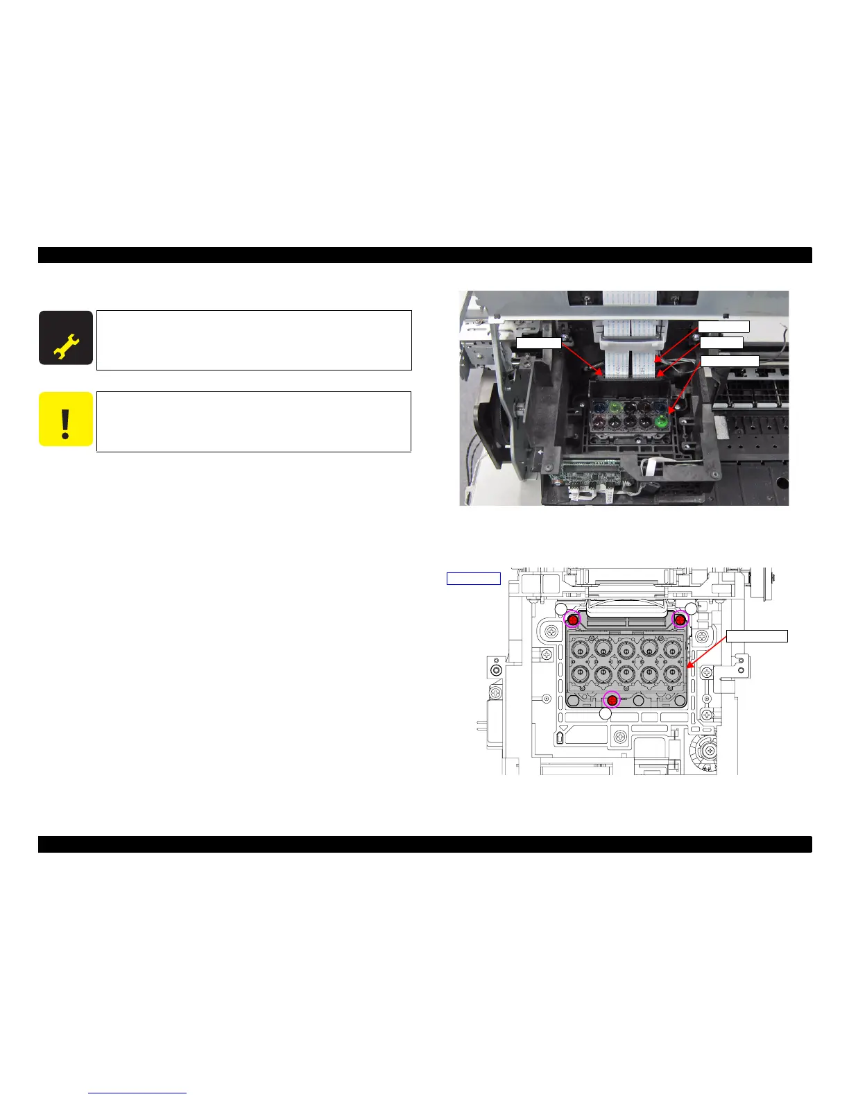
12. Disconnect the HEAD FFCs from the four connectors of the PRINT HEAD.
Figure 3-59. Removing the HEAD FFC
13. Remove the three screws, and remove the PRINT HEAD.
A) Silver M2.6x8 Machine screw: 3 pcs
Figure 3-60. Removing the PRINT HEAD
A D J U S T M E N T
R E Q U I R E D
When replacing/removing this part, refer to “4.1.2 Adjustment
Items and the Order by Repaired Part” (p199) and make sure to
perform the specified operations including required adjustment.
C A U T I O N
Be careful not to touch the nozzle surface of the PRINT HEAD.
PRINT HEAD
HEAD FFC
Connector
Connector
PRINT HEAD
A
A
A
Upper side
 Loading...