SC-T7000 series/SC-T5000 series/SC-T3000 series Revision B
DISASSEMBLY & ASSEMBLY Disassembly and Assembly Procedure 170
Confidential
3.4.5.5 PRESSURE ROLLER
1. Remove the UPPER LEFT COVER. (p100)
2. Remove the UPPER SUPPORT R COVER. (p94)
3. Remove the PANEL BOARD. (p120)
4. Remove the TOP COVER. (p85)
5. Remove the FRONT COVER. (p86)
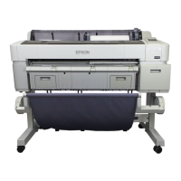
6. Rotate the Combination Gear 18.4, 37.6 counterclockwise to set the PRESSURE
ROLLER in the release position.
Figure 3-123. Rotate the Combination Gear 18.4, 37.6
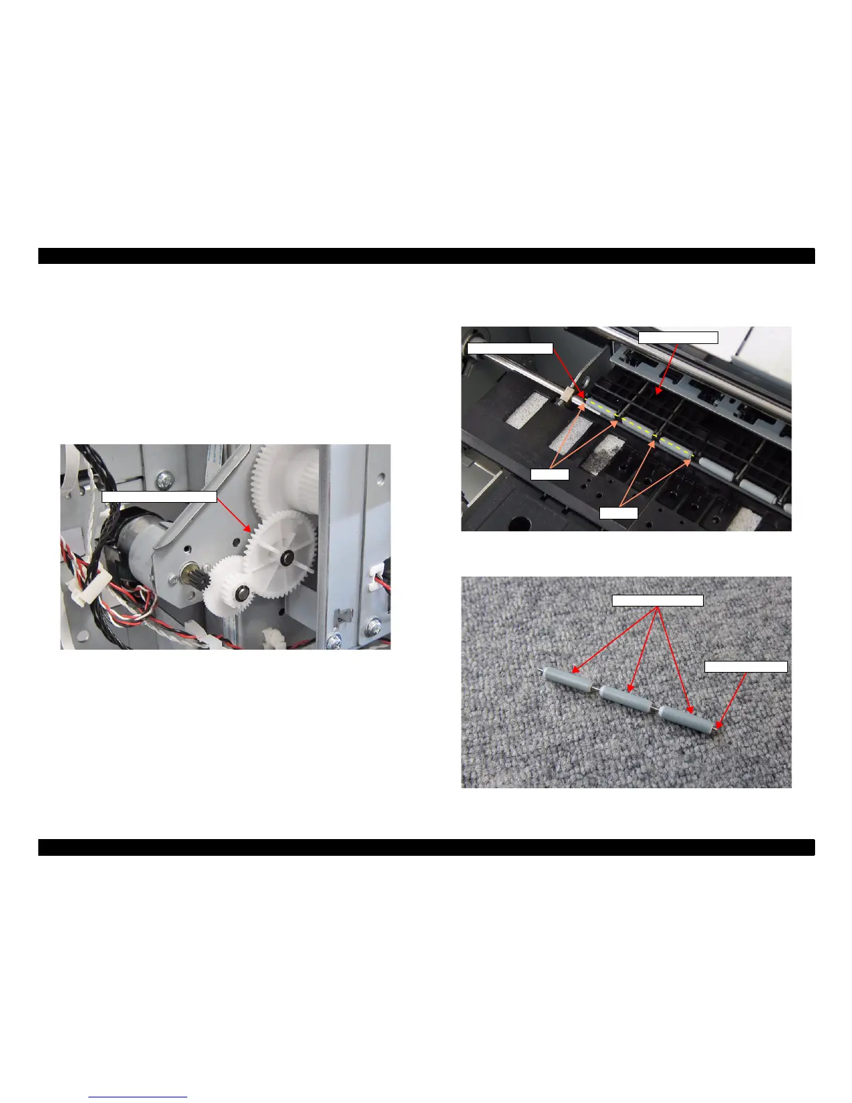
7. Remove the Pressure Roller Shaft from the four grooves of the Release Roller
Assy.
Figure 3-124. Removing the PRESSURE ROLLER (1)
8. Pull out the Pressure Roller Shaft from the three PRESSURE ROLLERs.
Figure 3-125. Removing the PRESSURE ROLLER (2)
Combination Gear 18.4, 37.6
Grooves
Release Roller Assy
Pressure Roller Shaft
Grooves
PRESSURE ROLLER
Pressure Roller Shaft
 Loading...